The ESP-01 Wi-Fi module is the most popular module in the ESP8266 series. Communication with a computer or microcontroller is carried out via UART using a set of AT commands. In addition, the module can be used as a standalone device, for this you need to upload your own firmware to it. You can program and upload firmware through the Arduino IDE version higher than 1.6.5. To flash the module, you will need a UART-USB adapter. The ESP-01 module can be widely adopted for use in IoT (Internet of Things) devices.
Specificationsmodule
- WiFi 802.11b/g/n
- WiFi modes: client, hotspot
- Output power - 19.5 dB
- Supply voltage - 1.8 -3.6 V
- Consumption current - 220 mA
- GPIO ports: 4
- Processor clock speed - 80 MHz
- Memory size for code
- RAM - 96 KB
- Dimensions - 13×21 mm
Connection
Consider the AT command mode. To do this, connect the module to the computer via a USB-UART adapter. Module pin assignment (see Figure 1):- VCC - +3.3V
- GND - ground
- RX, TX - UART pins
- Output CH_PD - Chip enable
- GPIO0, GPIO2 - digital pins
Figure 1. ESP-01 module pin assignment
Connection diagram for communicating with the module in AT-command mode (Figure 2):

Figure 2. Scheme of connecting the ESP-01 module to a computer via a serial port

Figure 3. Assembly diagram
To send AT commands in Mac OS X, you can use the CoolTerm program, in the Windows operating system, the Termite program. You can only find out the speed of the COM port for connecting to the module experimentally, it can be different for different firmware. For my module, the speed turned out to be 9600 baud. In addition, it was possible to establish the exchange only after disconnecting and reconnecting the CH_PD output to the power supply. After connecting, we type AT in the terminal and should receive an OK response from the module. The AT+GMR command issues the module firmware version number, the AT+RST command resets the module (see Fig. 4). A list of basic AT commands can be found in this document (ESP8266ATCommandsSet.pdf).

Figure 4. Sending AT commands to the module from the Termite program
If the AT command mode is not convenient for you, the board can be configured using the AppStack ESP8266 Config program, which can be downloaded from http://esp8266.ru/download/esp8266-utils/ESP8266_Config.zip . The appearance of the program is shown in Figure 5. The module is configured using a graphical interface, while the execution of commands can be seen in the program monitor (see Figure 6). The monitor can also send AT commands from the command line.

Figure 5. AppStack ESP8266 Config Program

Figure 6. Serial monitor of AppStack ESP8266 Config
There are two options for using this module:
- in conjunction with a microcontroller (for example, Arduino), which will control the module via UART;
- writing your own firmware to use the ESP8266 as a standalone device.
Usage example
Consider an example of connecting a DHT11 humidity and temperature sensor to the ESP-01 module and sending data to the ThingSpeak cloud service (https://thingspeak.com/). We will need the following details:- ESP-01 module
- bread board
- humidity and temperature sensor DHT11
- resistor 10 kΩ
- connecting wires
- power supply 3 - 3.6V

Figure 7. Scheme of connecting the DHT11 sensor to the ESP-01 module.
Then you need to create a profile in the ThingSpeak service. The service has instructions for sending data to the service and receiving data from the service.

Figure 8. Scheme assembled.
We will write the program in the Arduino IDE for ESP8266. We will use the ESP8266WiFi.h (built-in) and OneWire.h libraries. Let's upload the sketch from Listing 1 to the Arduino board - getting data from the temperature sensor and sending data to the ThingSpeak service. You need to enter your data for the WiFi access point for the ESP-01 module:
- const char *ssid;
- const char *password;

Figure 9. Graph of the DS18B20 temperature sensor readings in the ThingSpeak service.
Frequently Asked Questions FAQ
1. The module does not respond toAT commands- Check if the module is connected correctly;
- Check the correct connection of the Rx, Tx contacts to the UART-USB adapter;
- Check CH_PD pin connection to 3.3V;
- Select experimentally the exchange rate on the serial port.
- Check the correct connection of the DHT11 sensor to the module.
- Check the connection of the module to the WiFi access point;
- Check the connection of the WiFi access point to the Internet;
- Check if the request to the ThingSpeak service is correct.
To work with RemoteXY, the ESP8266 module must have a firmware version that supports AT commands no lower than v0.40. To check the version of the module, as well as to change the firmware if necessary, connect the module to the computer via the serial port. The module can be connected via an Arduino board or via a USB-UART adapter.
Connection via Arduino board
When using Arduino, the main ATmega chip is put into reset mode, only the built-in USB-UART converter remains active. To do this, the RESET pin is connected to ground. The RX and TX pins are connected directly to the ESP8266 instead of criss-cross, as if they were connected to work with the controller.
Connection via USB-UART adapter
The converter must have a 3.3V source output to power the ESP8266. Also, this source must provide the required current of at least 200mA.

The CPIO0 pin determines the module's operating mode. When the contact is not connected, the module operates normally and executes AT commands. When the contact is closed to ground, the module is switched to the firmware update mode. Putting the module into firmware mode requires that the CPIO0 pin be connected to ground when power is applied to the module. If the contact is closed while the module is running, the module will not switch to the firmware update mode.
Checking the current version
To send AT commands and view responses, you must use any serial port monitor program. The terminal program from the Arduino IDE is very good. The program must be set to send commands with a trailing line feed and carriage return. The default speed of the module is 115200 bps. For the module to work in the normal mode, the CPIO0 contact must be disabled.
You can check the current firmware version by executing the AT command: AT+GMR. Module response example:
AT version:0.40.0.0(Aug 8 2015 14:45:58)
SDK version:1.3.0
Build:1.3.0.2 Sep 11 2015 11:48:04
OK
It is also worth knowing the size of the flash memory of your module, the settings for data download addresses when updating the firmware depend on this. This manual describes the firmware of a module with a flash memory size of 8Mbit(512KB+512KB) or 16Mbit(1024KB+1024KB), as the most common. The size of the flash memory can be found by issuing the module reset AT command: AT+RST.
Ets Jan 8 2013,rst cause:2, boot mode:(3,1)
Load 0x40100000, len 1396, room 16
tail 4
chksum 0x89
load 0x3ffe8000, len 776, room 4
tail 4
chksum 0xe8
load 0x3ffe8308, len 540, room 4
tail 8
chksum 0xc0
csum 0xc0
2nd boot version: 1.4(b1)
SPI Speed: 40MHz
SPI Mode: DIO
SPI Flash Size & Map: 8Mbit(512KB+512KB)
jump to run user1 @ 1000
#t#n"t use rtc mem data
slЏ‚rlme
Ai-Thinker Technology Co.,Ltd.
Firmware program
To update the firmware, you need to download the program for the firmware and the firmware itself. The ESP8266 firmware will use Flash Download Tools v2.4 from the Espressif Systems official website. Link to the download page on the official website: . You need to go to the "Tools" section.
Link to the program in our file storage: FLASH_DOWNLOAD_TOOLS_v2.4_150924.rar
Firmware
The firmware can also be downloaded from the official website. Link to the download page on the official website: . You need to go to the “SDKs & Demos” section and download the ESP8266 NONOS SDK firmware version at least v1.3.0. It is from this firmware version that support for AT commands v0.40 and more is implemented.
Link to the firmware in our file storage: esp8266_nonos_sdk_v1.4.0_15_09_18_0.rar
All downloaded files must be unpacked and placed in a directory where the full path to the files consists only of Latin characters, that is, without language localization characters.
Setting
We launch the Flash Download Tools v2.4 firmware program (the .exe file of the same name). In the window that opens, you must correctly specify the downloaded files and the connection settings.

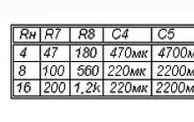
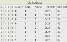
The downloaded files are located in the bin directory of the firmware archive. For each file, you must specify the correct download address. Use the following table to select files and assign addresses:
Set the following settings:
- SPIAutoSet - installed;
- CrystalFreq - 26M;
- FLASH SIZE - 8Mbit or 16Mbit depending on the size of the flash memory;
- COM PORT - select the port to which the ESP is connected;
- BAUDRATE-115200
To start the firmware, you must press the "START" button.
ESP8266 Firmware Steps
1. Connect the module to the computer according to the connection diagram in this article.
2. Start the serial port monitor. Issue the AT commands AT+RST and AT+GMR to determine the current firmware version and module memory size. This step also allows you to check if the module is connected correctly.
3. Launch the Flash Download Tools firmware, properly configure the downloaded files, set the settings.
4. Power down the ESP8266 module.
5. Connect the CPIO0 pin to ground.
6. Power up the ESP8266 module.
7. Press the START button in the firmware program
8. Wait for the module firmware to complete. At the end of the firmware, the inscription FINISH will appear in green.
9. Disconnect the power to the ESP8266 module. Disconnect the ground from the CPIO0 pin.
10. Turn on the module, start the serial port monitor. Make sure the module is working and the new firmware version is running the AT command AT+GMR.
... In general, this material is not limited to only one Arduino topic.
The topic of ESP8266 is rather complicated. But, if you work with these Wi-Fi modules in the Arduino IDE development environment, the entry threshold drops to an acceptable level for an ordinary arduinist. And not only an arduinist, but any person who has a desire to bungle something on the topic of IoT (Internet of things), and without spending a lot of time reading the documentation for the microcircuit and studying the API for these modules.
This video completely duplicates the material presented in the article below.
Well, we already know how to connect the ESP8266 and put it into programming mode, now let's move on to something more useful.
I will say right away - having programmed the module once in the arduino development environment, we demolish the native firmware, and we will no longer be able to work with the module using AT commands. Personally, this doesn’t make me cold / hot, but if someone needs it, towards the end of the article I’ll show how to flash the native firmware back into the module, or some kind of loader like NodeMcu.
To get started, download the latest version of the Arduino IDE on the offsite, at the moment it is 1.6.7. Older versions like 1.0.5. they won’t fit, because they simply don’t have the necessary functionality, and dancing with a tambourine doesn’t interest us, right?
We start the development environment and immediately go to File / Settings:

http://arduino.esp8266.com/stable/package_esp8266com_index.json
Then go Tools / Board: / Board Manager ...:

The board manager window will appear in front of us, scroll down to the very bottom, and if everything is done correctly, we will see something like this:

Click with the cursor on the inscription " esp8266 by ESP8266 Community"after that, we have the "Install" button, select the desired version, I take the latest one, today it is 2.1.0. and install it. The development environment will download the files it needs (about 150 megabytes) and opposite the inscription " esp8266 by ESP8266 Community""INSTALLED" will appear, i.e. installed:

We scroll down the list of boards and see that we have many different ESPs in the list, we take the "Generic ESP8266 Module":

We go to "Tools" and select the desired COM port (I have it COM32) Arduino or USB UART converter, then set Upload Speed: "115200":


We set the speed to 74880 and “NL & CR” and again turn it off and turn on the power and it will respond with some debugging information:

Note that 74880 is not the main speed of the ESP8266, it just sends debug information on it. If the module does not send anything to the console, then something may have been connected incorrectly.
By default, the speed should be 115200, but in some cases it may be 9600 and others ... So try to pick it up.

After selecting the desired speed, we send “AT” to the module and it should answer that everything is “OK”. The "AT+GMR" command displays information about the firmware.
Before you start flashing the ESP8266 in the Arduino IDE, I advise you to read the article to the end.
Now let's try flashing the ESP8266 through the Arduino IDE. We transfer the module to programming mode (I wrote how to do this in a previous article).
Let's sew the flasher with a regular LED:
// By MrPodelkinTs youtube.com/RazniePodelki // special to geektimes.ru/post/271754/ #define TXD 1 // GPIO1/TXD01 void setup() ( pinMode(TXD, OUTPUT); ) void loop() ( digitalWrite( TXD, HIGH); delay(1000); digitalWrite(TXD, LOW); delay(1000); )
Flashed? So everything is done right. Where did I get that the LED is connected to the first pin? In the previous article there is a picture with pinouts of different modules, and there is a markup of ports when using the Arduino bootloader (pins are marked in pink).

Flashing the LED is certainly good, but it would be necessary to close up some kind of web server or start controlling the LED at least with the help of buttons in the browser, right? But I will talk about this some other time.
And now how to flash back native firmware, and how to flash the module with third-party loaders. For ESP8266, there is such a program as NodeMCU Flasher, which was originally designed to flash the NodeMCU bootloader. But as it turned out, it perfectly flashes other firmware.
I will attach an archive with this program and firmware to the article for convenience, but you can always download the new version of NodeMCU Flasher.
There are 2 Win64 and Win32 folders in the “nodemcu-flasher-master” folder, and depending on what bit depth your OS has, select the one you need. Next, in the Release folder, run "ESP8266Flasher.exe" and see the program interface:

Select the desired COM port and go to the “Config” tab, remove the cross next to “INTERNAL://NODEMCU” and put it one point lower, as in the screenshot:

(If you want to flash the NodeMCU bootloader, remove the cross where it was not, and put it where it was, that is, near “INTERNAL://NODEMCU”).
Then we click on the gear and select where our firmware is located, the firmware is usually in * .bin format (in the attached archive it is “v0.9.5.2 AT Firmware.bin” which is in the main folder), and also select “0x00000” as and higher.

We return again to the “Operation” tab, transfer the module to the programming mode and click “Flash”:

Everything, the module began to flash, after flashing, do not forget to reboot the module and voila, it is flashed with the firmware we need.

We check with the AT command "AT + GMR" whether we did everything right:

As you can see, everything went well.
In the process of studying and designing more and more complex projects, there comes a time when there is a need and a desire to learn how to work with such a common type of connection as WiFi. Since it is this type of connection that can comfortably create a single network for your smart home devices and manage them, for example, from a mobile phone, tablet or computer, that is, in other words, create a real smart home that will cost you ten times cheaper than buy ready-made solutions in the store. The use of WiFi, of course, is not limited to this, and there are so many examples of using this type of connection that it makes no sense to list them, and if you got to this page, it means that you already needed WiFi for some reason, it remains only to figure out how to work with it correctly .
We will understand based on the cheapest and most popular WiFi module ESP8266-01. You can buy WiFi module ESP8266-01 on our website.
One of the main advantages of such a module is the presence of memory and its own microcontroller on the board, which allows it to work independently by loading the sketch directly into the module itself.
There are actually quite a lot of modifications to the ESP8266 WiFi module and we will not list them here, having learned how to work with one, you can easily start working with others. I would like to note right away that working with WiFi may seem like a rather difficult task, and if there are few completed projects in your luggage, it’s better to give up WiFi connection for now and use radio communication in your projects, which is much easier to understand. Entire communities and thematic forums are created to work with WiFi modules, which once again proves how difficult it is for most people to immediately deal with this type of connection, and rereading all the information, most people simply give up. Most likely, I will not be able to fit all the important information within the framework of this article alone, and there is no point in this, otherwise another confusion will result. I will try to follow the path of a strict sequence of the most important points so that you can begin to understand the principle of operation of this type of communication and then simply develop your skills in this direction on your own.
And so, let's get started and first analyze the conclusions of the WiFi module ESP8266-01.

VCC- module power supply from 3V to 3.6V
GND- land.
RST- Reset output responsible for module reloading.
CH_PD- "chip power-down" when power is applied to it, the operation of the module is activated.
TX- data transfer (UART interface)
RX- data reception (UART interface)
GPIO0
GPIO2- general purpose I/O port
The GPIO0 and GPIO2 pins are exactly the same digital pins that we work with on Arduino boards for interfacing with various sensors, and they are used in the case of implementing independent work on the internal WiFi microcontroller of the ESP8266-01 module.

To reliably power the ESP8266-01 module, use an external regulated 3.3V power supply and better not try to take power from your Arduino board, as the module draws up to 215mA current and this may end badly for your development board. Where can I get a stabilized 3.3V power supply, I hope it's not a problem for you, otherwise it's obviously too early for you to deal with this module. For example, I like to use this YWRobot 3.3V and 5.0V power supply module to quickly collect circuits on breadboards, which allows you to quickly get a stabilized voltage at 3.3V or 5V on the corresponding breadboard power tracks.
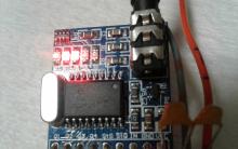
We connect plus (+) from our 3.3V power supply to the output VCC module ESP8266-01, and minus (-) bring the power supply to the output GND. In this state, the red LED on the module will turn on, signaling us that the power is connected correctly. In order for the module to activate, you must also connect the plus (+) output power supply CH_PD module ESP8266-01 and it is desirable to do this immediately through a 10kΩ resistor. Now, when we turn on the power, the red LED on the module should light up and the blue LED should blink quickly a couple of times. If this is what happens to you, then everything is fine, you connected everything correctly and your module is working. Otherwise, check the connection again, or replace the module, since it is most likely not working.
Go ahead. To work with the ESP8266 WiFi module, we need a USB-UART adapter. Adapters are different, for example: FT232RL, CP2102, PL2303. But we will assume that you do not have such adapters, and we will use the Arduino board as a USB-UART adapter. I will be using an Arduino NANO board for this, or you can use any other board you have. The connection on any board is one to one identical. We make the connection according to the following diagram.
 Let's take a look at what we've done here. Immediately pay attention to the fact that we shorted the terminals on the Arduino board with a jumper RST and GND. Such manipulation turns off the microcontroller and allows us to make a real USB-UART adapter out of our Arduino board.
Since we are powering the ESP8266-01 WiFi module from a separate external power supply, remember that we must always connect the ground of all power supplies in our projects. So we connect the output GND Arduino boards with ground (-) our external 3.3V power supply, designed to power the ESP8266-01 module.
Conclusion TX of your Arduino board we connect to the output TX ESP8266-01 module. This line will transmit data from the WiFi module to the Arduino board. Those who are familiar with the UART interface may think: "But how is it? Everywhere they taught that TX should be connected to RX. TX transmits information, and RX receives." And you will be right. That's right, TX is always connected to RX, but it is in the case when we make a UART adapter from Arduino that it is necessary to connect devices directly. Consider this the exception to the rule.
line RX your Arduino board is also connected directly to the line RX ESP8266-01 module. This line will transmit information from the Arduino board to the WiFi module board. But we make this connection through the so-called voltage divider, consisting of two resistors with a nominal value of 1 kOhm and 2 kOhm. We need to reduce the voltage on this line using two resistors (voltage divider), since the Arduino board transmits a logic signal with a voltage of 5V, and the WiFi module operates with a voltage of 3.3V. To convert the logic signal, we could use a special logic level converter scarf, which would of course be more correct, but again, let's assume that you don't have it, and we had to go the simpler way and do it with a voltage divider.
We have connected everything necessary for further work, but we still have 3 more outputs that are not involved ( GPIO0, GPIO2 and RST) on the WiFi module ESP8266-01. For the stable operation of the WiFi module, we need to pull these remaining unused conclusions to the positive (+) power supply lines of the module through 10 kOhm resistors.

This will save us from various interferences (pickup) and make the module work stable. It's better to do it right away. Otherwise, don't be surprised that your module is constantly reloading, giving out incomprehensible information, or not wanting to work at all. Using pull-up resistors on unused microcontroller pins should be the rule of thumb if you want stable performance in your projects.
And again, we check the performance of the WiFi ESP8266-01 module. We turn on the power and see that the red LED lights up and the blue blinks a couple of times. If that's the case, then great, let's move on. Otherwise, we check the correctness of the connections, as well as the quality of all contacts. It may just be a banal situation, when everything was double-checked ten times and made sure that everything was connected correctly, but turning on the module, you see that the blue LED does not behave adequately, is constantly on, constantly blinking, or does not react to anything at all. This may be due to poor contact on some line. For example, when assembling a circuit on a breadboard, one of the resistors is loose in place and this causes noise. Check the quality of the connections. The module is very sensitive. Don't neglect it. This is a common cause of unstable operation.
In general, we are done with the connection. Now we need to prepare the Arduino IDE program to work with the ESP8266-01 WiFi module. To do this, we need to download and install the necessary archive with libraries, examples and ESP boards in the Arduino IDE, which will later allow us to upload sketches directly to the microcontroller of the ESP8266-01 module, change the firmware, etc. In the framework of this article, we most likely will not need these settings, but it seems to me that after we figured out how to connect the module, the procedure will be correct if we immediately download everything you need to work with the Arduino IDE. Everything is basically simple here.
We start the program Arduino IDE and go to the menu "File" - "Settings"


In the window that appears, in the upper field, write "esp8266". As a result, in the window we will have only the necessary firmware. When you click on the firmware, a button will appear "Installation". Click on the button "Installation" and wait until everything is set. The archive is quite large, about 150 megabytes, so you'll have to wait.

After finishing the installation. We restart the Arduino IDE and see how the new ESP boards appeared in the "Tools" - "Boards" menu. That's all. We are done with setting up the Arduino IDE. So far, we do not need these settings, but in further work we cannot do without them.
We have connected and prepared everything, now we can begin to deal with the controls. In fact, now there will be a continuation of checking and configuring the module using AT commands, and there is no way to do without it. WiFi modules are implemented in such a way that all communication with them takes place using the so-called AT commands, which are hardwired into the module's firmware. We will not list all AT commands here, there are quite a lot of them, and if you want to study everything carefully, you can easily find them on the Internet. And we will use now only the most necessary to get started.
And so, we connect our Arduino board via a USB cable to the computer. And an external power supply that powers WiFi module ESP8266-01 until you turn it on. We launch the Arduino IDE program, select our Arduino board in the "Tools" menu, in my case it is Arduino NANO, and you choose yours. Also, do not forget to select the port to which our Arduino is connected. I hope you understand and know how to do all this.
Open port monitoring "Tools" - "Port Monitor". Choosing a port speed 74880 (the module starts at this speed) and select "NL & CR" on the left in the list

Now we connect an external power source that feeds our WiFi module. After that, you should see something like this in the port monitor.

Here we see some information about our WiFi module (speed, amount of memory on board, etc.). The received information may differ depending on the firmware version of the WiFi module. Let's not focus on this. Something else is important. At the bottom we see a set of meaningless characters, this means that the port speed (74880 baud) that we have set is only suitable for the initial loading of the module to see this information normally, but this speed is not suitable for normal communication with the WiFi module.
To select the correct port speed, we will simply change the port speed and send characters to the port (top field and send button) AT until we get an answer OK. If you try to send symbols right now AT port at speed 74880, you will receive another one or two meaningless characters in response.

Try to immediately set the speed to 115200 baud and send the AT command. Most often, modules are flashed at this speed.

This is what you should see in your port monitor. If you still receive an incomprehensible set of characters in response, slow down and resend AT commands until the answer is returned OK. If you tried all the speeds and did not get the correct answer, then you are out of luck and the module is flashed with firmware at a non-standard speed. Then it remains only to reflash the module with normal firmware, but this is a topic for a separate article.
I hope that everything is fine and you have chosen the right speed. By the way, if you try turning the WiFi module off and on again after you have chosen the correct speed, then instead of the very initial information that was correctly displayed at 74880 baud, you will, on the contrary, see a chaotic set of characters, but at the end you will see the word "ready ". But we have the opportunity to see this initial information in a normal form at the correct speed, for this we need to programmatically reload the module using the AT command AT+RST.
To find out the firmware version of your ESP8266-01 WiFi module, you need to send the command to the port monitor AT+GMR and in response you will receive something like the following information:

WiFi module ESP8266-01 can work both in access point mode and in client mode. To allow the module to work in all modes at once, send the command to the port monitor AT+CWMODE=3 and in return you should get OK.
Team AT+CWLAP will allow you to view all WiFi access points that your module currently sees. My module, for example, currently sees only three WiFi access points in its coverage area. The answer should be something like this:

For example, we know the password to the third access point and to connect to it we execute the command AT+CWJAP="name","password", in my case this command looks like AT+CWJAP="dsl_unlim_512_home","11111111", to which we get a successful response:

The command parameters are written to the flash memory of the ESP8266-01 WiFi module, and if we turn off the module and turn it on again, it will automatically connect to this access point. Look by chance in the command do not allow a space, otherwise you will receive a response ERROR. It should be noted that in the latest firmware versions it is recommended to use the command AT+CWJAP_CUR, that is, the command will look like AT+CWJAP_CUR="name","password". If suddenly we forgot which access point our module is connected to, we need to send a command AT+CWJAP? or AT+CWJAP_CUR? and in response we will get the access point to which the WiFi module is connected at the moment.
With connection and initial setup WiFi module ESP8266-01 we figured it out. The module is working and ready for the implementation of your further projects. It is simply not possible to analyze all possible examples of working with this module within the framework of one article, and we will deal with this in the following articles. And for those who are not very friendly with programming, but really want to quickly start managing their projects using WiFi, I recommend introducing them to the RemoteXY WiFi project designer. This site will help you easily create a control interface for your mobile phone or tablet and use it to control your device to which you connect the WiFi module.
How to use the ESP-01 module to control the LED via the Internet, a module that allows you to control any electrical device.
In this ESP8266 tutorial, we are using the ESP-01 module to control an LED over the Internet. ESP8266 is a cheap but effective platform for communicating over the Internet.
It is also easy to use with Arduino. After completing this lesson, you will have the basic knowledge of controlling any electrical device via the Internet from anywhere in the world!
Here we will use the USB-to-TTL converter to program the ESP8266 ESP-01. And we will use to develop a web server to control the LED remotely.
How it works
The ESP8266 can be controlled from a local Wi-Fi network or from the Internet (after port forwarding). The ESP-01 module has GPIO pins that can be programmed to turn an LED or relay on or off over the Internet. The module can be programmed using the Arduino USB-to-TTL converter via serial pins (RX, TX).

Connecting Hardware to Your ESP8266
We can use a USB-to-TTL converter or use an Arduino to program the ESP8266. Here are three ways you can follow to upload code to your ESP8266 - choose the one that suits you best. Refer to the diagrams for each option and set up your equipment accordingly.
1. USB-to-TTL converter using DTR connector
If you use a USB-to-TTL converter with DTR output, the download will run smoothly. Please note that the serial monitor will not work with this.

USB TTL → ESP8266 ESP-01
GND → GND
TX→RX
RX → TX
RTS → RST
DTR→GPIO0
2. USB to TTL converter without DTR output
In order to connect a USB to TTL converter without a DTR pin, we must use manual transmission. We use two buttons for this - see the following diagram:

USB TTL → ESP8266 ESP-01
GND → GND
TX→RX
RX → TX
Reset Button → RST
Flash Button → GPIO0
When downloading the code, click the "Downloads" (Flash) button. Keep the button pressed while you press the Reset/Reset button once. Now you can release the Flash button. The ESP8266 is now in a mode where you can upload a sketch.
3. Using Arduino Uno to upload code to ESP8266
You can use ESP8266 ESP-01 to run the code. When downloading the code, follow the same procedure as in the second point - keep the "Downloads" button pressed as you click reset once, and then release the Flash button.

ARDUINO → ESP8266 ESP-01
GND → GND
TX → TX
RX→RX
Reset button → RST
Button Flash → GPIO0
ESP8266 code download
Use any of the above methods and open , then select the ESP8266 board from the menu:
Tools → Board → Generic ESP8266 Module
(Tools → Board → ESP8266 Module)
Note. If you have not installed and configured the Arduino ESP8266 board, please do so by following the steps above in this guide. Then you can move on.

Now copy the code below into the Arduino IDE and click the upload button. Change SSID to wifi hotspot and change password to your wifi password and compile.
#include
"); client.println("Click here turn the LED on pin 2 ON
"); client.println("Click here turn the LED on pin 2 OFF
");client.println(""); delay(1); Serial.println("Client disconnected"); Serial.println(""); )
Open the serial monitor and open the URL shown on your serial monitor through a web browser. Connect GPIO 2 from ESP8266 to the longer LED pin. Now you can control the LED remotely via the Internet!


Remove any wires that were needed to download the code. The LM1117 module is used to provide a regulated 3.3V output. This will allow you to make the ESP8266 or ESP-01 module standalone.

Connecting the ESP8266 to the Internet
Currently, the ESP8266 module is only accessible via LAN Wi-Fi. To manage devices from the Internet, you need to perform port forwarding on your router.
To do this, find your system's IP address either using the "ifconfig" command in your terminal or go to whatsmyip.org. Copy your IP address. Now open the router setting and go to the "Forwarding" settings. Enter the details for "Service Port" and "IP Address". The service port is the port number from your Arduino code (service port: 80):
WiFiServer server(80);//Service Port
The IP address is the one you specified earlier. Leave the rest of the default settings. Now go to your browser and enter the address: xxx.xxx.xx.xx:80. The page for controlling the LED should open.


 How to remove kgb spy if you forgot your password")


Tips&Tricks in Adobe illustrator: Tricks in illustrator
Windows won't boot after installing updates
Windows won't boot after installing updates
AVG Internet Security - free license
AVG Internet Security - free license