New Articles
● 5.4. Expansion of digital ports for NodeMCU ESP8266 using MCP23017 chip
We will introduce LED indication and sound alarm when using the Nodemcu module as a smart home controller. The number of pins on the Nodemcu module is much less than on the Arduino Mega, so we need the MCP23017 input expander IC. The MCP23017 chip adds 16 ports that can be configured for both input and output (Figure 5.7). The chip uses the popular two-wire I2C bus.
Rice. 5.7. MCP23017 pinouts
The address of the MCP23017 chip for the I2C protocol can be set by a combination of signals at the digital inputs A0 - A2 (Fig. 5.8), which allows you to connect 8 MCP23017 chips to the microcontroller at the same time, respectively 16*8=128 pins.

Rice. 5.8. Setting the address of the MCP23017 chip
The chip has 2 banks of ports A (GPA0-GPA7) and B (GPB0-GPAB), each of which can be configured for input or output.
Listing 5.3. shows an example of setting up output banks A and B.
Listing 5.3
// connecting the Wire.h library #includeThe use of the MCP23017 chip will expand the number of digital contacts of the Nodemcu module by 16 and will allow organizing LED indication and audible signaling of critical sensor parameters.
Everyone loves inexpensive Arduino boards, but so often a project is literally missing one or two free ports! And sometimes there are enough ports, but you don’t want to pull a bundle of wires to another part of the structure. Suppose you need to place several buttons and LEDs on the front panel of the device. It is more reliable and easier to connect them to the main board with just two data bus wires, and not with a cable or a harness, right?
For such situations, various expanders (expanders) of Arduino ports are designed.
Typically, microcontroller pins implement several different functions, so expanders are different:
- Standard GPIO Port Expander
- PWM output expander
- Analog input expanders - multiplexers and external ADCs
Separately, it is worth mentioning digital-to-analog converters (DACs) and expanders of the I2C bus address space. These devices do not directly duplicate the functions of ports, but expand the capabilities of microcontrollers.
In the first article of the series, we will talk about the simplest and most useful expanders that work as digital I / O ports. These are microcircuits and. They are arranged and work absolutely identical, and differ only in the number of ports.
Choosing an expander module for Arduino
The most popular and inexpensive module is made on the PCF8574 chip (Fig. 1)
Rice. 1. Popular PCF8574 port expander module
Advantages:
- Low price.
- Modules can be connected in a chain by simply inserting the plugs of one module into the sockets of the previous one. Don't forget to set jumpers to different module addresses!
Disadvantages:
- Cannot be inserted directly into a breadboard (I recommend soldering the port connector to the back side).
- A total of eight ports in one module.
If you are in the mood for more serious projects, order a 16-bit module for PCF8575 on Aliexpress. I strongly recommend the module shown in Fig. 2.
Rice. 2. PCF8575 port expander module
Advantages:
- Twice as many ports.
- Built-in 3.3V power supply, you can power other modules.
- Built-in logic level matching for the I2C bus at different supply voltages.
- Convenient format for a breadboard.
Disadvantages:
- Above price.
How the PCF8574/PCF8575 GPIO Port Expander Works
Data exchange takes place via the I2C bus. Only four wires are required to connect to the Arduino board, including power. The expander address is set by three jumpers on inputs A0…A2, so eight identical chips can be connected to the bus at the same time and get a maximum of 8*8=64 additional ports with PCF8574 or 8*16=128 with PCF8575 chip.
To output data to the port, write a data byte to the address of the module on the I2C bus. To read data from a port, read a byte at the same address. A byte is always written and read as a whole, work with individual digits is done programmatically.
The outputs of the microcircuit are simultaneously inputs, and there is no service register that determines the purpose of the output. There is only a latch in which the output byte is written. How is this possible?
The ports operate in an open-collector manner and have internal pull-up resistors. If a logical zero is written to the output, then the output transistor opens, which forcibly pulls the output “to ground”. Reading from such a port will always return zero.
Be careful when applying a direct supply voltage to a pin with a low level or if the current is exceeded 50 mA you will ruin the chip!
To use a port as an input, write a one to it. In this case, the internal transistor will be closed, and the result of the read will be determined by an external logic level applied to the pin. The free output is pulled up to power by a built-in resistor.
In order to simultaneously use some of the ports as inputs and some as outputs, before each data byte is written to the expander, it is necessary to apply a mask of units to those bits that correspond to the inputs using the “logical OR” operation. That's all)))
Interrupt generation
PCF857* Port Expanders Generate Interrupt Pulse low level at the INT output with any change in the input signal at any input of the microcircuit. This is convenient if the expander serves a keypad. But you must determine in the interrupt handler which button was pressed or released. The interrupt generator is equipped with a chatter suppression filter.
Example 1: Using the PCF8574 module
Let's assemble a simple circuit of four LEDs, a PCF8574 module and an Arduino board (Fig. 3 and 4). With this switching scheme, we do not even need quenching resistors for LEDs. Current flows through the LED and the built-in resistor connected to the power rail.
Rice. 3. Wiring diagram of the PCF8574 module
Rice. 4. Circuit layout with PCF8574 module
Copy and paste sketch 1 into the Arduino board:
A high level is initially written to all ports of the microcircuit, so ports P0 ... P3 can work as inputs.
The levels on the port pins are read every 500 ms and the reading result is displayed on the monitor. If you connect one of the P0…P3 inputs to a common wire, zero appears in its bit. Then the read value is shifted to the left by four bits, the result is output to the port and one of the LEDs goes out. For example, if zero is read at pin P0, then the LED connected to pin P4 will turn off.
Please note that before each write to the expander, we must apply a bit mask of ones to all bits that should be inputs: dataSend |= B00001111;
Subroutines for working with the I2C bus are extremely simplified, no errors are processed.
Advice: to find and check the module address on the I2C bus, you can use . It outputs to the terminal the addresses of all devices that respond to a bus request.
Example 2: Using the PCF8575 module
The peculiarity of the PCF8575 module is that it has 16 ports, so it always write two bytes and read two bytes. This rule must be observed even if the second byte is not needed.
Let's change the schema a bit. We will connect the LEDs to the ports P10 ... P13, and we will connect the ports P00 ... P03 with a jumper to the common wire (Fig. 5 and 6).
Rice. 5. Wiring diagram of the PCF8575 module
Rice. 6. Circuit layout with PCF8575 module
Sketch 2 first writes ones to all ports, then reads their state every 500 ms. The read procedure returns a 16-bit word that is divided into bytes. The content of the low byte (pins P00…P07) is copied to the high byte and uploaded back to the module. If one of the outputs P00…P03 is connected to a common wire, then one of the LEDs connected to P10…P13 will go out.
// Library for working with I2C #include
Arduino Library for PCF8574/PCF8575
The library can be downloaded from GitHub. But, as you can see, working with port extenders is very simple and you can easily do without a special library.
One of the key advantages of the Arduino platform is its popularity. The popular platform is actively supported by manufacturers of electronic devices, releasing special versions of various boards that expand the basic functionality of the controller. Such boards, quite logically called expansion boards (another name: arduino shield, shield), serve to perform a wide variety of tasks and can greatly simplify the life of an arduinian. In this article, we will learn what an Arduino expansion board is and how it can be used to work with a variety of Arduino devices: motors (motor driver shields), LCD screens (LCD shields), SD cards (data logger), sensors (sensor shield ) and many others.
Let's first understand the terms. The Arduino expansion board is a complete device designed to perform certain functions and is connected to the main controller using standard connectors. Another popular name for an expansion board is the English-language Arduino shield or simply shield. All the necessary electronic components are installed on the expansion board, and interaction with the microcontroller and other elements of the main board occurs through standard arduino pins. Most often, the shield is also powered from the main arduino board, although in many cases it is possible to power it from other sources. In any shield, there are a few free pins that you can use at your discretion by connecting any other components to them.
The English word Shield is translated as a shield, screen, screen. In our context, it should be understood as something that covers the controller board, which creates an additional layer of the device, a screen behind which various elements are hidden.
Why are arduino shields needed?

Everything is very simple: 1) so that we save time, and 2) someone could make money on it. Why waste time designing, placing, soldering, and debugging something that you can take already assembled and start using right away? Well-designed and assembled on high-quality hardware, expansion boards are usually more reliable and take up less space in the final device. This does not mean that you need to completely abandon self-assembly and do not need to understand the principle of operation of certain elements. After all, a real engineer always tries to understand how what he uses works. But we will be able to make more complex devices if we do not reinvent the wheel every time, but focus our attention on what few people have solved before us.
Naturally, you have to pay for the opportunities. Almost always, the cost of the final shield will be higher than the price of individual components, you can always make a similar option cheaper. But here it is up to you to decide how critical the time or money spent is for you. Taking into account all possible assistance from the Chinese industry, the cost of boards is constantly decreasing, so most often the choice is made in favor of using ready-made devices.
The most popular examples of shields are expansion boards for working with sensors, motors, LCD screens, SD cards, network and GPS shields, shields with built-in relays for connecting to the load.
Connecting Arduino Shields
To connect the shield, you just need to carefully "put" it on the main board. Usually, the pins of the comb-type shield (male) are easily inserted into the Arduino board connectors. In some cases, it is required to carefully tweak the pins if the board itself is not soldered neatly. The main thing here is to act carefully and not apply excessive force.
As a rule, the shield is designed for a very specific version of the controller, although, for example, many Arduino Uno shields work quite well with Arduino Mega boards. The pinout on the mega is made in such a way that the first 14 digital contacts and the contacts on the opposite side of the board coincide with the location of the contacts on the UNO, so the shield from arduino easily becomes it.
Arduino Shield Programming
Programming a circuit with an expansion board is no different from the usual programming of an arduino, because from the point of view of the controller, we simply connected our devices to its usual pins. In the sketch, you need to specify those pins that are connected in the shield to the corresponding pins on the board. As a rule, the manufacturer indicates the correspondence of the pins on the shield itself or in a separate connection manual. If you download the sketches recommended by the board manufacturer, you won't even need to do that.
Reading or writing shield signals is also done in the usual way: using the functions, and other commands familiar to any arduinist. In some cases, collisions are possible when you are used to this connection scheme, and the manufacturer has chosen another one (for example, you pulled the button to the ground, and on the shield - to power). Here you just need to be careful.
As a rule, this expansion board comes in arduino kits and therefore it is with it that arduino people meet most often. The shield is quite simple - its main task is to provide more convenient options for connecting to the Arduino board. This is done through additional power and ground connectors, brought to the board to each of the analog and digital pins. Also on the board you can find connectors for connecting an external power source (you need to install jumpers to switch), an LED and a restart button. Shield options and usage examples can be found in the illustrations.


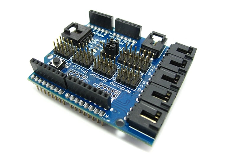

There are several versions of the sensor expansion board. All of them differ in the number and type of connectors. The most popular versions today are Sensor Shield v4 and v5.
This arduino shield is very important in robotics projects. Allows you to connect regular and servo motors to the Arduino board at once. The main task of the shield is to provide control of devices that consume a current that is high enough for a regular arduino board. Additional features of the board are the function of controlling the motor power (using PWM) and changing the direction of rotation. There are many varieties of motor shield boards. Common to all of them is the presence in the circuit of a powerful transistor through which an external load is connected, heat sink elements (usually a radiator), circuits for connecting external power, connectors for connecting motors and pins for connecting to an arduino.


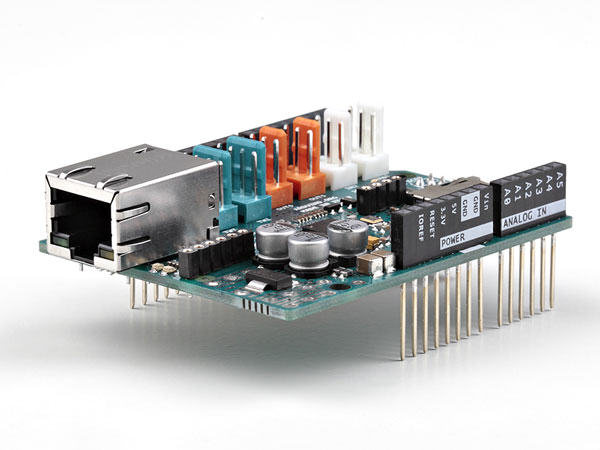
The organization of work with the network is one of the most important tasks in modern projects. To connect to a local area network via Ethernet, there is a corresponding expansion board.


Prototyping Expansion Boards
These boards are quite simple - they have contact pads for mounting elements, a reset button is displayed and it is possible to connect external power. The purpose of these shields is to increase the compactness of the device, when all the necessary components are located immediately above the main board.


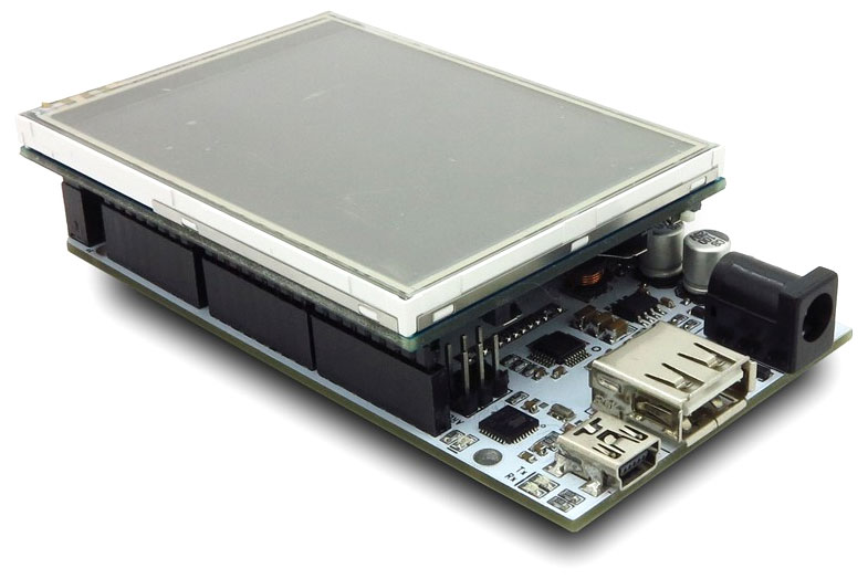
Arduino LCD shield and tft shield
This type of shield is used to work with LCD screens in arduino. As you know, connecting even the simplest 2-line text screen is far from a trivial task: you need to correctly connect 6 screen contacts at once, not counting the power supply. It is much easier to insert a ready-made module into an arduino board and simply upload the corresponding sketch. In the popular LCD Keypad Shield, from 4 to 8 buttons are immediately connected to the board, which allows you to immediately organize an external interface for the user of the device. TFT Shield also helps


Arduino Data Logger Shield
Another task that is quite difficult to implement on your own in your products is the storage of data received from sensors with time reference. The ready-made shield allows not only to save data and receive time from the built-in clock, but also to connect sensors in a convenient way by soldering or on the circuit board.


Brief Summary
In this article, we have considered only a small part of the huge range of various devices that expand the functionality of arduino. Expansion boards allow you to focus on the most important thing - the logic of your program. The creators of the shields provided for the correct and reliable installation, the necessary power supply. All that remains for you is to find the board you need using the cherished English word shield, connect it to the arduino and upload the sketch. Usually, any programming of a shield consists in performing simple actions to rename the internal variables of an already finished program. As a result, we get ease of use and connection, as well as the speed of assembly of finished devices or prototypes.
The downside of using expansion cards is their cost and possible loss of efficiency due to the versatility of shields that lies in their nature. For your specific application or end device, all of the shield's features may not be needed. In this case, you should use the shield only at the stage of prototyping and testing, and when creating the final version of your device, think about replacing it with a design with your own scheme and layout type. It's up to you, you have all the possibilities for the right choice.
→ How to expand the number of analog inputs and outputs on your Arduino?How to expand the number of analog inputs and outputs on your Arduino?
A multiplexer or demultiplexer will allow you to expand the number of inputs and outputs on your Arduino.
The 4051 is an 8-channel analog multiplexer/demultiplexer, thus:
* If you are using the 4051 as a multiplexer: You can select any of the 8 different inputs and read its status to the controller.
* If you are using the 4051 as a demultiplexer, you can select any of the 8 different outputs and write the value you want there.
Also, 4051 can handle analog values, in your Arduino, you can use 0-5V analog signals and connect the IC to analog inputs on Arduino.
To select the desired microcircuit input as well as read or write operation modes, we must use three control signals (S0, S1 and S2). Each of these pins must be connected to one of the Arduino's digital outputs. Each output has a number (S0 = 1; S1 = 2; S2 = 4) and if one of these outputs is set to a high logic level then the number of pins represented will be 4051.
For example:
* If you set log “1” at the inputs of the microcircuit S0 and S1 and log “0” at S2, then the input y3 of the microcircuit is selected, it looks like this (1 +2 +0 = 3).
* If you set log “1” at the inputs of the microcircuit S0 and S2 and log “0” at S1, then the input y5 of the microcircuit is selected, it looks like this (1 +0 +4 = 5).
It is not possible to read or write status to more than one 4051 pin at a time. But you can read and write the state from the output of the chip fairly quickly. There is no need for a delay between selecting, reading or writing the state of the 4051 pins.

* Z----- common input or output signal (connected with Arduino I/O)
* E ----- enable input (active log "0") (connected to ground (GND))
* Vee --- negative supply voltage (connected to ground (GND ))
* GND --- ground negative (0 V)
* S0-S2 - select inputs (connected to three Arduino digital pins)
* y0-Y7 - independent inputs/outputs
* Vcc --- positive supply voltage (5V)


The left image above is an example of how to use a 9 multiplexer to read 64 analog inputs with only one Arduino analog input.
The right image above is an example of how to use two 4051s (one configured as a demultiplexer and one as a multiplexer) in an 8x8 matrix to test 64 buttons or other digital inputs from just one digital input on the Arduino (from the second setup you can just have two buttons at a time). same time, otherwise you should use the first (left) setting).

Code example:
// Example for using 4051 analog multiplexer/demultiplexer
// by david c.
int led = 13 ; // Set up the LED on the 13th leg
int r0 = 0 ; // value select output to 4051 (S0)
int r1 = 0 ; // value select output to 4051 (S1)
int r2 = 0 ; // value select output to 4051 (S2)
int row = 0 ; // store the bin code
int count = 0 ; // brush
int bin = ( 000, 1, 10, 11, 100, 101, 110, 111 ) ; // An array of binary numbers defining the number of the selected input / output of the 4051 chip, from 1 to 8.
void setup () ( // INITIALIZE
pinMode (2 , OUTPUT) ; // s0 exit
pinMode (3 , OUTPUT) ; // s1 exit
pinMode (4 , OUTPUT) ; // s2 exit
digitalWrite (led , HIGH) ; //light the LED
beginSerial(9600) ; // UART exchange rate
}
void loop()(
for (count = 0 ; count ≤ 7 ; count ++) ( // cycle through array elements from 1 to 8
row = bin [ count ] ;
r0 = row & 0x01 ;
r1 = (row >> 1) & 0x01 ; //
r2 = (row >> 2) & 0x01 ; //
digitalWrite(2, r0) ;
digitalWrite(3, r1) ;
digitalWrite(4, r2) ;
Serial.println(bin);
delay(1000) ;
SPI or I2C ADC chips are readily available in a range of resolutions, sample rates, and number of channels. They are fairly easy to add to any Arduino.
For example, the MCP3208 will give 8 channels of 12-bit resolution per SPI, which means 3 pins (MOSI/MISO/SCK) + 1 per chip (SS). So 1 chip will be 4 pins, 2 chips 5 pins, 3 chips 6 pins, etc.
Adding a lot of ICs to the SPI bus though can be a nuisance in and of itself with the increased capacitance of all those inputs meaning you need to slow down the messaging speed a bit or add some extra buffering to drive the bus more heavily.
I2C chips can be trickier to have as there are only a limited number of addresses on the I2C bus - plus on many Arduinos I2C is also two analog pins that you might not want to sacrifice.
The second option involves using analog multiplexers (eg 4051) to switch different sources to the existing analog inputs.
The third option, which you probably haven't considered, is to have multiple arduinos (or other inexpensive microcontrollers) each doing some fetching and then implementing some method of communication between them (or with a single master). This has the added benefit of being able to sample multiple channels at the same time (one per microcontroller), which speeds up your work somewhat.
Expanding on Mazhenko's answer, you can use an analog multiplexer like the 74HC4051 to turn one analog port into 8.
Its cousin, the 74HC4067, will multiplex 16 ports. Now with 6 analog inputs on the Arduino Uno you can have 6 x 16 inputs = 96. The A/B/C control signals can be in parallel.
This will allow you to handle 96 inputs with 6 extra chips and fairly simple code. I have code examples on my 74HC4051 mux/demux page.
For 8 inputs code:
// Example of using the 74HC4051 multiplexer/demultiplexer // Author: Nick Gammon // Date: 14 March 2013 const byte sensor = A0; //where the multiplexer in/out port is connected // the multiplexer address select lines (A/B/C) const byte addressA = 6;//low-order bit const byte addressB = 5; const byte addressC = 4; //high-order bit void setup()( Serial.begin(115200); Serial.println("Starting multiplexer test..."); pinMode(addressA, OUTPUT); pinMode(addressB, OUTPUT ); pinMode (addressC, OUTPUT); ) //end of setup int readSensor (const byte which) ( //select correct MUX channel digitalWrite (addressA, (which & 1) ? HIGH: LOW); //low-order bit digitalWrite (addressB, (which & 2) ? HIGH: LOW); digitalWrite (addressC, (which & 4) ? HIGH: LOW); //high-order bit //now read the sensor return analogRead (sensor); ) / /end of readSensor void loop () ( //show all 8 sensor readings for (byte i = 0; i< 7; i++) { Serial.print ("Sensor "); Serial.print (i); Serial.print (" reads: "); Serial.println (readSensor (i)); } delay (1000); } //end of loop
I worked exactly with the same issue. I need a program that reads 100 thermistors... Why? well, if you need it.
I already finished it.
I tried the 74HC4051 multiplexer/demultiplexer. But for some reason I didn't get the desired result.
The first thing you will find... POWER, you will need an external power supply, in my case I just made a voltage divider and connected the thermistor to that power and then just use the analog port to read...
I am using I2C protocol, 8 arduino Mega 7 slaves and one master. and after sending send Integer, float and blah blah didn't work for me to just do it. It can send an analog read over I2C and the master does all the necessary conversion.
If you are still interested, I can send you the source code for master and slaves. With this template, you can connect up to 50 arduinos and the master will look for each arduino connected on the network and request data.


Wargame: Red Dragon not starting?
Sad escobar "The face of the judicial system of Ukraine"
ROME Total War - how to unlock all factions?
How to turn off the TalkBack feature?
Overview of alternative firmware HTC Desire A8181 Bravo How to install the firmware file for HTC Desire