It is one of the most important components of a car. The functioning of the device and the indicator of the communication range depend on how correctly the selection of the device was carried out.
Today, there is a wide range of products on the market that differ in design, size and technical parameters. A car enthusiast will always be able to choose the right model for himself.
The right choice is the key to the success of your radio station.
What is a radio antenna for?
The car radio antenna ensures optimum radio reception. But which model should you choose? It all depends on your needs. Some are content with listening to radio broadcasts only, others - television broadcasting, others prefer the presence of a navigation system. Therefore, before purchasing, it is advised to decide on your budget, the technical data of the device and the place of its installation.
Antennas for VHF radio stations
Car antennas for domestic VHF radio stations are represented by a variety of models. When choosing a device, you should stop your attention on the manufacturer "Triad". This Russian company represents a wide range of devices that are distinguished by a high degree of functionality, reliability, and reasonable price.

The development and selection of antennas takes place within the same enterprise, which allows you to control the process at all stages. The key to the high quality of the product lies in the long-term experience of the company, as well as the timely equipment of the production base.
An excellent choice for many motorists can be the Triad VA 63-01 radio antenna model. This device is equipped with a rod, the length of which is 40 cm. It provides reception comparable to an antenna with a length of 70-100 cm. The coiled wire provides a high level of functionality that exceeds many of the shortened models.
A similar antenna with a rod 45 cm long is installed on such car models as Chevrolet and Niva as standard luxury equipment. It is recommended to install it on the front of the roof of the car. The device is sealed and waterproof.
You can list several features of the antenna mentioned above:
- It replaces the regular mortise model for cars of domestic and foreign production.
- Its mortise installation is carried out on the wing or roof.
- The tilt angle is from 0 to 90 degrees.
- VHF, FM, AM waves are received.
"Murena 27 MHz"
The car antenna for a radio station of a domestic manufacturer has a great appearance. Its height is 15 cm. The model is able to provide a high level of purity of signal reception. Pre-setting is easy: the top of the instrument has a screw that can be adjusted with a standard screwdriver.
Positive aspects of the product:
- attractive design;
- low response to interference;
- compactness;
- high level of protection against bad weather.
But in the case of painting in a bright color, the antenna becomes similar to special means, which will surely attract the attention of the traffic police. And the level of efficiency is significantly lower than that of standard analogues, the length of which is 150 cm.
"Scat AV-23" - a radio antenna at an affordable price
This car radio antenna is of high quality and reasonable price. Thanks to the stabilizer in the design, it is not afraid of voltage drops. The device has a small amount of extraneous noise and interference. The package includes a cable length of 275 cm. This allows you to mount the device in a new way.
Product advantages:
- the device functions well both in a large city and in the region;
- main wires are shielded;
- there is a blue backlight;
- the product has an attractive appearance.
There is only one minus of the device - the presence of thick antennae for attaching the device. They stand out on the windshield.
Foreign analogue of FM Calearo ANT 7727085
For a car radio from an Italian manufacturer, installed on the roof, it will allow you to receive radio waves, watch digital television broadcasts and catch GPS signals. The package includes two 5 m cables for TV and GPS.

The company promises optimal signal reception - with proper configuration and installation, this is really achievable. The antenna is presented in different colors: white, black and red models.
- universal device;
- attractive appearance;
- practicality of use (easy to clean);
- the antenna itself is short and does not touch the branches;
- the mass of the device is small, it is 440 g.
- high price;
- to connect a TV tuner, you need to purchase additional wiring;
FM cord not included
SIRIO T3-27 MAG - the best magnetic car antenna
The device from the Italian manufacturer is distinguished by a small height and an optimal level of work. A magnet on a stainless steel pin provides easy attachment to the car body. The antenna functions with civil radio stations. The maximum input power is 100W.
Device advantages:
- compact and lightweight fixture (weight 400 g);
- the presence of a screw for adjusting the height (the device can be extended by 3 cm).
- the design is unstable at high speed (above 120 km/h);
- the device is narrow-band and does not work without tuning.
Calearo ANT 76 77 901 - a good outdoor car antenna
This antenna also has an attractive design. It is mounted on the back of the roof at an angle of 60 degrees. The required voltage for operation varies from 10 to 16 watts. The length of the rod is 41 cm.
- high signal level;
- high-quality mount that allows the device to be in a stable position even at high vehicle speeds;
- the presence of high protection against interference;
- strong body.
- if the regular hole did not fit, then the installation of the antenna is difficult and you have to drill the roof;
- the device requires timely cleaning from dust and dirt.

Which radio antenna to choose
Many are wondering which antennas are best for a radio station (car). Choosing a model with optimal technical parameters and a high level of functionality is not an easy task, so we advise you to seek help from people who understand this matter. The main thing is to clearly imagine for what purpose you decided to purchase the device.
If you are the owner of the most ordinary radio in the car and, apart from the radio, you practically do not need anything, then it makes no sense to buy a fancy device that is far from cheap. It will be enough to purchase the same Skat.
If you, for example, are a taxi driver, then it will not be superfluous to purchase a more serious model. Do not forget about the important fact that the radius of high-quality reception of modern models of radio antennas, despite the assurances of manufacturers, is rarely higher than 40 km.
It is important to correctly install and configure the device.
How to make a radio antenna with your own hands?
Do-it-yourself antenna for a car radio station is quite simple. The main thing here is saving money, and the quality of a handicraft device is in no way inferior to a purchased analogue. And to make a radio antenna with your own hands, you must prepare:
- anchor bolt;
- welding machine for cold welding;
- copper wire.
Progress
A copper wire should be wound onto the anchor bolt along its entire length. The winding is carried out in two layers. Solder the wire over the bolt. The resulting structure is screwed into the socket of the device located on the roof of the car.
Work with cold welding is carried out only with gloves that are wetted with cold water. This will make it possible to avoid them sticking to the skin of the hands.
The base of the antenna is sealed with a transparent self-adhesive film to avoid contact with plastic. Cold welding is applied to the rod evenly so that it becomes even.
In order for the antenna to be given an aesthetic appearance, after solidification, the rod is processed with emery. If the surface is rough, then you need to unscrew the bolt and machine it on a lathe. The surface is primed and covered with several layers of paint to match the color of the car. Matte paint is preferred. It can hide all the irregularities on the surface of the product.

A homemade car antenna for a radio station will serve you for decades. It is perfectly mounted on any car model and receives radio waves even far from a large settlement.
Typical misconceptions of users and errors in installing radios and antennas on a car
The main principle of antenna installation: when choosing the "best" antenna, do not put it in the "worst" conditions! If it is not possible to install perfectly, take the antenna shorter, but put it correctly. The efficiency will be much better than installing a long antenna coiled into a ring due to lack of space!
The following misconceptions degrade the quality of communication to a DIFFERENT degree.
Antenna tuning
You need to understand that ANY car antenna bought in a store is a HALF antenna. The other half is your car. Therefore, the antenna is tuned exclusively on the car, at the place of further location. By the way, many advanced buyers ask to adjust the antenna when selling. However, this cannot be done without installing it on the car (at the place where it will be used in the future). If you transfer an antenna tuned to one vehicle to a vehicle of another model, the antenna becomes untuned. The tilt of a tuned antenna turns it into a non-tuned one. Removing and installing a tuned antenna in the same place does not change the quality of the tuning!
Many users, having removed the antenna for the radio, which was at an angle to the roof surface, put the communication antenna in the same place in the same position. This is a mistake, because receiver antennas for radio tape recorders are specially designed for a specific installation configuration. And its parameters are selected for the desired size and slope. Transceiver whip antennas (including 27 MHz) are initially designed for vertical installation! Deviation from this position must be very carefully corrected by tuning, but it is not a fact that this can be overcome, because. even with good SWR, the antenna will work upwards, not horizontally, and it may turn out that a good connection will be with Kazakhstan due to reflection from the ionosphere, and not within a radius of 10 km along the highway.
Installing an antenna without ground
One of the most common mistakes when installing antennas (any whip antennas, not just 27 MHz) is to install the antenna "without ground". As a rule, a driver who installs an antenna on his own uses worldly experience, and when installing, he only thinks that the antenna should stand higher and hold on tight.
As a result, we see:
- antennas mounted on structures that do not have contact with the car body;
- antennas embedded in plastic;
- deliberately isolated from the body.
For antennas installed without mass, the maximum radiation pattern (radiation / reception direction) has a significant angle to the horizon. As a result - a short range, more interference from the car's network. Particularly inquisitive owners of walkie-talkies, when studying the possible causes of short range, having learned that "mass" is needed, begin to throw all kinds of "mass veins", not knowing that they can significantly change the circular nature of the radiation pattern and matching. Therefore, if there is any doubt about the installation method, it is better to contact specialists.
There are no complaints about the installation method, because. in some cases there really is nowhere else to put the antenna. BUT: in this case, a MAN TGA car is shown, on which there is no mass on the mirror arc! This is a rare case when it is possible and necessary to use a mass core (short and thick, from the base of the antenna to the bolt of the mirror arc to the door). Here the mass vein is not laid. Here's a little nuance. If it was depicted Kamaz, then everything would be correct.

Iveco Stralis car. The antenna is mounted on a mirror mount (plastic). Throw a massive vein on the bolt. It would be more correct to install the antenna in a regular place under the visor, which is 20 cm from the mirror. When the antenna can be installed without a mass core, it must be installed without it. In this example, the vein is very thin and long.
Installing the antenna on the rail

Such solutions are one of the classic installation options with an absolute misunderstanding of how the antenna works. Many people think that it just needs to be screwed to something. As a rule, roof rails do not have contact with the ground (but there are exceptions). If the bracket has contact with the railing, and the railing has no contact with the ground, then the working (underlying) surface of the antenna is only the railing.

This antenna is embedded in the searchlight crossbar. In this case, the antenna is shorted to ground with a bolt and is not an antenna, but simply part of the body. The result is an antenna with a non-circular directivity, with maxima to the right and left along the railing. It will work badly back and forth. The range in this case is 20-50 m. The life of the transmitter of such a radio station, if other aggravating conditions are imposed, can be several seconds!


There is no mass initially in both cases. On the left, installation on plastic, in the photo on the right, the antenna is installed on special insulating gaskets. However, for contact with the ground, a mass core (white cable) was forwarded and this problem was eliminated.
At installation on spoilers and plastic surfaces
Special care is required, as often spoilers do not have contact with the metal body of the car. And installation even on metal parts does not give a guarantee in obtaining "mass". In the absence of a metal roof or other convenient metal substrate, the antennas are mounted on counterweights that imitate the "ground". Such antennas work less efficiently than those mounted on a metal surface, because. for proper operation, the counterweights must be the same size as the base 27 MHz antennas (i.e. about 50 cm). Counterweights press the lobes of the radiation pattern to the ground, increasing the range. Some radio owners, who have studied the theory of radio communication at their leisure, install counterweights (smaller, that is, a different range) for the prevention of short range, including even magnetic ones and antennas embedded in a metal roof. Such a variant of "improvement" has not been studied in detail, and how much (and whether) the change in the diagram has occurred cannot be visually tracked, theoretically, no one has done this, but we are sure that there will be no significant effect.

Car - Freightliner ("American"). On this bolt there were cases of spontaneous loss of mass.

IVECO car (Eurostar or Eurotec). Antenna tilt too high. At this point, the mass can be obtained by stripping in the right places. Initially, it is not on plastic.

If the roof were not metal, it would be possible to do this, although the effect would not be great, because. counterweights of another range are demonstrated.
Amplifiers and walkie-talkies of high power.
To get a longer range, users are trying to increase the output power of the walkie-talkie for amplifiers intended for installation mainly at the walkie-talkie output up to 4 watts. Applying more power to the input of the amplifier may lead not to an increase, but rather to a decrease in the output power of the "radio station-amplifier" complex.
- The use of an amplifier with an untuned antenna leads to the fact that the output power actually increases, but it does not leave the antenna. We have repeatedly demonstrated to customers
advantage of a 4 W station with a well-tuned antenna over a 90 W amplifier with an untuned antenna.
- Using an amplifier for an untuned antenna for a long time leads to overheating of the station and, as a result, burnout of the output stage as a result of a sharp increase in power returning from the antenna to the radio station output.
- Most buyers don't bother learning how an amplifier works, because the most acceptable amplifiers have a switch button for operation in amplitude or frequency transmission, and the user, having turned on the amplifier in FM mode, works as a walkie-talkie in AM modulation. Inconsistent modes do not give an increase in power and lead to strong signal distortion.
- Amplifiers are effective in urban areas, where due to the re-reflected from metal products (garages, roofs, cars ...) they can provide an increased range of up to 5-7 km. When working with base stations (for example, in St. Petersburg it is a paid service "Scream"), high power is very important and 10 W at a distance of 20 km is really not enough. But on the highway, where there are not so many metal objects, but there is a Russian terrain, your 50-100 W output power will not help you and you will be in the same ranges as the 4 W stations (namely: 5- 10 km).
- Selling cheap amplifiers are very unreliable:
- They break down quickly and are expensive to repair;
- Sellers do not give a guarantee on them !!!;
- Not coordinated with the radio station, they distort the sound, cause noise.
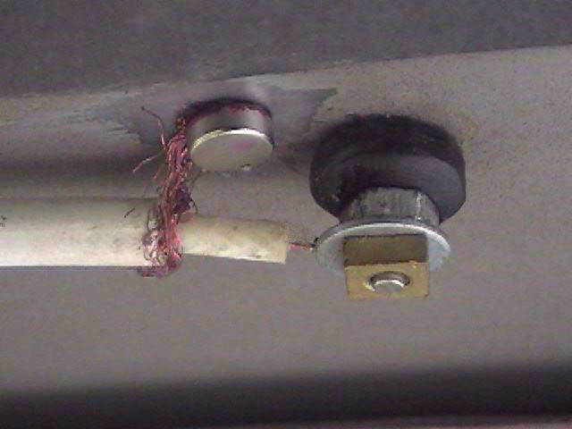
Antenna weather protection

In this case, the antenna connector is smeared with lithol (solidol) (according to the owner) and wrapped with tape. Bolt-through antennas are indeed very susceptible to oxidation when mounted on a bracket. Do not smear with oil or light materials, because. when heated, they can penetrate the connector and break the contact. Lithol is a good waterproofing agent. It is enough to pour lithol or silicone sealant into the protective cap (fill completely), and then put it on. But adhesive tape is superfluous, because. in this "bag", on the contrary, water, condensate accumulates, and the appearance deteriorates.

The same applies to magnetic antennas put in plastic bags. We do not recommend using methods that bring much more corrosion than you expected.

The second option came from Poland. Basically, we met such decorations on trucks. To improve ventilation, we would recommend making small vertical cuts in the upper part.
Installing the antenna near metal structures.
Due to the lack of free surface, the antenna is often placed next to metal structures. This also applies to trunks and platforms of car carriers. Any whip antenna for both the walkie-talkie and the radio is affected by all surrounding objects. They greatly change the tuning and radiation pattern of the antenna despite the seeming insignificance of the dimensions.


On the drain is an antenna for the radio. The radio antenna is embedded in the roof. In this case, the fact that they touch each other (even if there is no electrical contact) can greatly degrade the tuning of BOTH antennas.
Apparently, the antenna for the radio was falling all the time, and the driver decided to fix it that way. The reception of the radio is unlikely to become noticeably worse, because. within the city, the radio tape recorder catches on the wiring thrown out onto the street, but the radio has lost up to 30-40 percent of the range.

Antenna for radio. Not only did the antenna originally serve as a holder for something, because. some hooks are tied to it, and the excess cable is wrapped around a metal core (side-view mirror stand), and a cable connected to the car body is also attached to the antenna pin! It is not even possible to guess what idea the owner of the antenna was implementing, and what kind of super connection he was counting on.
Fig. 1: A blunder is that the pin should not touch anything metal. If there is an electrical contact, then this is a short circuit to ground, if not (Fig. 2) - then this is a strong detuning of the SWR and a strong change in the pattern.


Radio antenna. In the city, the signals are so strong that they can be caught even without an antenna, so all errors will appear when the signal is weakened and your radio will become useless on the border of the city, and not 100 km from it.

What is possible for receiving antennas is not allowed for transmitting. An antenna mismatch during transmission can cause the radio to overheat.
Installing the antenna at a low angle to the surface.
The antennas in both cases run parallel to the frontal surface of the cabin at a distance of approximately 7 cm from the underlying surface. This leads to a deterioration in SWR even for an initially tuned antenna up to 3-5 and a strong distortion of the radiation pattern. This is not allowed for transmitting antennas!


Antennas are curved. Such an installation example is shown in the movie "Jurassic Park", which is not correct.


Installing the antenna below the level of metal surfaces.
1. BELOW ROOF LEVEL:
The fear of damaging a long antenna leads to its installation on the side walls of the body, between the cab and the van, etc. There is not only a non-symmetrical radiation pattern, but also an incredibly poor SWR. Even when setting up such an antenna, you cannot get a long range. This is a variant that combines the two previous errors.


In both cases, the antenna is installed in such a way that a metal frame or a metal casing of a plastic body is located behind and much higher than it. In addition, in the latter case, installation was also made on the railing! It is unlikely that there is a mass. You can only sympathize with the quality of communication! In MAZs, KAMAZs, we strongly recommend that you embed antennas in the roof.
2. BELOW TRUNK LEVEL:

The radio antenna needs a "ground" for good communication, but in the city the signal is so strong that reception will be on wires of any length.

Antenna 27 MHz. The lack of "ground", shielding by the trunk wall negate the gain from using a good long Alan 9 Plus antenna.
Changing the angle of the antenna when the car is moving.
Decorating a flexible antenna with various objects leads to an increase in windage and, as a result, inertia. The antenna sways more than without load. Due to this fluctuation during movement, the SWR changes. With some settings, SWR fluctuations occur from 1 to 10. In this case, the radio is a candidate for combustion, not to mention the quality and range of communication.


The use of two antennas per radio.
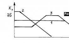
Based on everyday practice, some believe that if one head is good, and two are better, then two antennas (tracker) pick up a signal better than one. However, the use of trackers is quite controversial, because. the radiation pattern of the paired antennas is not omnidirectional. If everything is done correctly, then the DN of the trackers looks like in fig. The antennas are located on the sides of the vehicle and are marked with bold dots (top view). We see that the RP maxima are directed forward and backward of the car, and the minima are along the axis connecting the two antennas. It turns out that we have a gain in amplification forward and backward, and to the sides - up to the absence of communication, i.e. A narrowly directional antenna, not a circular one!
Because Since our roads are by no means straight, at the slightest turn in the road, communication may be lost. However, if you set exactly this task, i.e. increasing the forward and backward range along the vehicle, then this is true ... ideally ... provided that:
The distance between the antennas is 1/4 wavelength (2.75m),
The lengths of the cables to each antenna are exactly the same.


At the slightest violation of these main conditions, a reversal of the DP in the UNKNOWN direction is observed. Setting up such a system is very difficult, because is determined not only by the SWR parameter of EACH antenna, but also by the LENGTH of the cable from the adder to the radio and much more, the study of which is absolutely not worth the result.
Some users put symmetrical identical antennas by connecting one to the radio (tuning the antenna to this range). The effect for the radio exceeds all expected. But this spectacle misleads everyone else.
Set and forget.
Most users do not realize that over time there is a change in the properties of the system, consisting of a walkie-talkie, antenna, connectors, cable, mount.
- At the antenna, the pin is loose;
- The walkie-talkie has a connector that connects it to the antenna;
- Contacts are oxidized;
- Fasteners oxidize, weight is lost;
- The cable is pinched, erased, numb, loses its tightness from temperature changes.
This happens even with mortise antennas, not to mention those mounted on fasteners.
Therefore, it is advisable to inspect and prevent the system when changing the season (i.e. 2 times a year): strip connectors, fasteners, tighten connectors, ring the cable, etc. If this is not done, then at some point the range and quality drop, and the radio burns out, although initially it was set up and everything was done according to the rules.


Building a simple fm radio antenna with your own hands is a great way to improve the quality of the received radio signal. First, let's deal with replacing a standard antenna with a dipole one.
Most modern radios are equipped with sockets for connecting conventional antennas - both built-in and external telescopic ones. You can make a high-quality radio antenna without resorting to high costs, just a single visit to a regular hardware store is enough, and, of course, you need to know what a radio antenna can be made of.

Work materials
- Ceramic insulators and elements for their connection. They are necessary in order to prevent the antenna cable from shorting to adjacent surfaces. You can buy these devices at any radio market or find them in some abandoned building.
- Thin steel wire for connecting insulators.
- Roller blocks needed to fix the external radio antenna in a taut position.
- Antenna connector.
- A two-position switch designed to protect against thunderstorms.
- A coil of copper wire with a diameter of 1.5 to 2 millimeters. You can, of course, use steel wire, but copper is much more pliable and more convenient.

Antenna type
Now let's decide on the type of radio antenna being assembled. There are three main types of antennas for an FM receiver suitable for DIY assembly, the diagrams of each of them are shown below:
- Line antenna
- Antenna with a traveling surface wave
- Aperture antenna, that is, an antenna with a turn.


Instructions on how to make an antenna
The installation of any horizontal type antenna begins with the choice of a support, to which we will later attach the insulators. The first support should be on the roof of the house, and for the second, you can choose a tree with the appropriate height. We attach the insulators to the racks using steel cables.


The outer part of the antenna should not be pulled too tight, as when the air temperature drops, the wire shrinks and can break.


Roller blocks are used to reduce vibrations. To use them, you need to fix a small load on the opposite end of the wire, connecting it to the antenna.


The receiving element of the future antenna must be a single piece of a single material. If there is no whole piece of wire, then several elements can be combined from a single material by stripping and soldering with tin solder.


The mount for the vertical receiving element of the antenna is a stand that prevents the wire from changing position during strong winds.


If there is very little space for placing the antenna, then the design can be modified: we cut the wire into several pieces and connect the end of each of them with molten tin to the cable. The place of soldering must be securely isolated. Below is a photo of a homemade antenna suitable for fm radio.


The best replacement for the trap would be a homemade indoor antenna. In this case, the insulators are mounted indoors, while as close to the ceiling as possible (this is recommended to improve signal reception), and the wire is pulled horizontally or folded into a spiral.


Fabrication of a resonant frame antenna
Such antennas are often used by mechanics to receive shortwave signals. For directional signal reception, the antenna is simply turned in the right direction. Such designs allow you to receive radio signals much more clearly thanks to magnetic elements.

So, how to make a similar antenna for fm radio at home? First you need to find a hoop made of aluminum with a diameter of 77 centimeters and a cross section of 17 millimeters, you can get one in any sporting goods store.

If the hoop could not be found, you can use plumbing pipes made of plastic and metal, or a copper tube with a diameter of 1.6 cm.

The assembly sequence of such a design is extremely simple:
- We solder the central core, the winding and a piece of coaxial cable to the contacts of the capacitor with a variable capacitance.
- We solder the other end of the cable, the central core and the winding to the aluminum hoop. You can also use a car clamp, which must first be cleaned at the mating site.
- The dimensions of the structural elements are calculated in such a way that the length of the frame, in this case the hoop, is five times the length of the connection loop.
- From one end of the cable and from the central core, we remove the insulation layer by about one centimeter.
- We remove the insulation in the middle of the cable, having previously canceled 5 millimeters from it in each direction. Then we remove the cable braid, since the above actions will lead to its rupture.
- We adjust the range of our radio receiver so that the design has a resonance of 5-22 MHz. With a different value of the capacitance of the capacitor, the parameters of the receiving-transmitting device can be changed.
- Depending on the desired received range, you can change the frame parameters. So, for receiving low frequencies, we select the diameter of the hoop within one - one and a half meters, and for receiving high frequencies - 70 centimeters.

These simple rules will allow you to build a device that can operate in different ranges.

conclusions
We have presented to your attention the simplest and most popular ideas and drawings of antennas for fm radio, suitable for self-assembly. Most of these designs are extremely simple both in installation and operation, and will allow you to easily solve many household tasks.

Photo antenna for fm radio


Today, car antennas have various purposes. In combat time, they catch communications, and in peacetime - navigation information and broadcast channels. Due to the simplicity of the design, a car antenna can be made independently. More on this later in the article.

They call a special device that receives electromagnetic radio signals and converts them into an electrical signal. To make an antenna for a car with your own hands, you need to decide on the type of modulation, the wavelength range and the purpose of the device. These are the three key components that are incorporated into the design.

Types of car antennas for their intended purpose

Types of car antennas by installation method

Types of car antennas according to the place of attachment and type of amplification
By type of amplification, the following types of car antennas are distinguished:

Place of attachment:

The principle of operation of a car communication antenna
The size of the car antenna directly depends on the range. That is why 27 MHz communication antennas are so large. The most powerful variations are capable of reaching two meters in length, however, according to the rules of science, they should be even higher. To adjust the differences between a quarter wavelength and the actual size, there is an extension coil at the base.

A communication antenna is installed on cars strictly vertically, due to the type of polarization. It is worth noting that all communication antennas are able to tilt by means of a lever in certain road conditions, for example, in order to overcome the span of a low bridge or not to break in the forest. As a rule, communication antennas are used by owners of large trucks. Mounting on jeeps and other cars is allowed, but the view will not be very attractive.

Digital car antenna, principle of operation
Digital car antennas for TV reception, as a rule, look like police flashing lights, but are made in a different color scheme. There is nothing complicated in their device, they just have to receive a frequency of about hundreds of MHz. For example, the first multiplex in Moscow is located at a frequency of 559 MHz.

Digital car antennas on a magnet, as a rule, are placed on the roof, and the wire runs directly above the door without any modifications. The signal is distinguished by the presence of horizontal polarization, the main task of the device is to receive it from each azimuth.
broadcasting antenna

Broadcasting antennas are both "flashing lights" and pins of small height, like those that receive radio signals, but a little shorter.
Technical characteristics of radio, television, navigation, radio communication frequencies
- Radio communication - SV (about 27 MHz).
- Navigation - GPS (about 400 MHz).
- Television - DVB-T (up to 900 MHz).
- Radio - FM or AM (about 70 - 108 MHz).

Also pay attention to the connector. As a rule, it matches most of the devices for which it is intended, but it will not be superfluous to check this. There is an opinion that an external antenna catches better, but this only applies to reception in the city. On country roads, the glass of an ordinary passenger car is not capable of creating serious obstacles. However, in-car antennas are easier to install. It is worth noting that they are lower than outdoor ones, which affects the quality.

There are various hybrid models on the market. In addition, it is possible to switch reception from city to highway. Their difference is in the features of interference suppression and sensitivity, due to which the reception range outside the city is significantly increased. There are also peculiar tandems - a pair of similar-looking pins, the first of which is television broadcasting, and the second is radio or communications. Of course, in order to take full advantage of the kit, you need to have the appropriate receiving equipment available.
Tools, materials and fixtures to help the master

DIY car antenna, step by step instructions

It is worth saying that the body of the car is constantly in motion. That is why ordinary terrestrial household antennas will have dead reception zones in this case. When maneuvering, there will be quite long periods of time when there will be no reception. This refers to horizontal polarization. With vertical, it doesn't matter where the signal comes from.

When self-manufacturing a car antenna, a frame structure is used, which must be laid under the seal of the rear window of the car. It is slightly narrower towards the top and has slightly different dimensions than required at a frequency of 27 MHz. That is why a capacitor is located in the center, which tunes the car antenna on the desired channel to resonance.
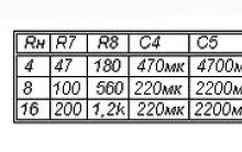
There are two receiving frequencies, for example:
- 28.2 and 68 MHz
- 27 and 65 MHz.
The upper resonance is for the lower broadcasting range. Car Antenna Diagram:
- It is necessary to lay the MGTF 0.5 wire in a trapezoid along the perimeter of the rear window - sidewalls 22.5 + 22.5 and 45 cm, lower edge 66.5 + 66.5 cm, upper edge 56.5 + 56.5 cm.
- The pluses are where the wires for the corresponding capacitor will be added and the signal taken with the PK-50 cable.
- Two wires run vertically to the center, in the middle, of the glass, where a tuning capacitor is attached exactly in the center. The length of each is 45 centimeters. They need to be twisted in a zigzag and laid under an insulating tube.
- The cable must be soldered from the sidewall, where the wire is cut in the middle. There should be no gap on the opposite side.
How to install and connect the antenna
The car antenna is connected via the connector used by the communication equipment. Take a short cable length.

Advantages of a do-it-yourself antenna
Such models, as a rule, are installed on the roof of the car and have a greater height than the passenger car itself. In the forest, this is a definite plus. Moreover, there is no need to wind the matching device. In this case, ease of design, ease of installation and accessibility to any user are achieved.

In some cases, purchasing a car antenna and installing it is more expensive, more difficult, and provides poorer reception. There is nothing complicated in the design below, and every motorist can try it in action.
SB radios (CB, "CB") are those that operate in the civilian frequency range, namely 27 MHz. Registration is not required to use this device. The frequency is divided into a so-called channel grid. In the early days of radio communication, there were only 40 channels. But after this amount was not enough, they began to break up and designate with alphabetic characters. Thus, the correct setting of the radio requires the correct installation of channels.
Radio communications are actively used by taxi drivers and truckers as more reliable than mobile communications. There is no need to pay the operator for a call, to depend on its coverage network. But as a minus, you can call a limited range, as well as the possibility of interference and congestion of the channel.
But if you choose and configure the antenna for the walkie-talkie correctly, you can achieve high-quality stable communication over a wide distance. Of course, the range also depends on the equipment itself. Somewhere it is 5–7 kilometers, but there are models with more than 20 km. But the importance of a good antenna is often underestimated. But in many ways it is she who determines the range of signal reception. Do not rush to buy a very expensive radio, it may be that such a price is due to the presence of a large number of functions that are not always needed. And when you connect a good antenna to fairly budget equipment, you will achieve the same result.
Antennas for car radio can be divided by type of installation:
- on mortise;
- magnetic.
The mortise antenna is mounted in the body. Moreover, when installed on a hood or fender, it loses its effectiveness by 30-40%. You need to install as far as possible from vertical metal parts that are parallel to the base of the antenna.
Magnetic antennas do not require tie-in, and are usually used on cars. On large trucks, they may fall off due to vibration. Such an antenna for a walkie-talkie can be easily installed and removed, transferred to another car.

And also antennas for car radios differ in size:
- Long with a pin of about 2 meters, create the highest quality and stable connection.
- Medium ones from 90 to 170 cm, have a lower gain and work at a shorter distance. But they are more convenient because they do not touch such upper obstacles as bridges, tree branches, power lines.
- Short 65–70 cm, comfortable and not so noticeable, but providing a short reception range.
The most effective are long mortise. But even a good antenna needs proper installation and tuning.
Installation
An important factor in a good signal is the correct installation of the antenna:
- Attach to the top of the body on a stable base.
- Installation on bumpers, doors, mirrors reduces efficiency.
- Install vertically unless otherwise stated in the instructions. If you need to install at an angle, you must first mount and then adjust. It is in this order, and not adjust, and then tilt.
- The surface area on which the installation is made should be as large and flat as possible.
- Try not to put on the hood and trunk.
- The antenna itself and the connecting cable must be located as far as possible from sources of interference, such as the ignition system.
Setting
Before using the antenna for a walkie-talkie, it must be configured. If this is not done, you will not receive the declared reception quality indicators. Setting instructions:
- The adjustment must be made under the same conditions as the operation of the vehicle. That is, among other cars, and not in the garage.
- Mount the antenna securely to the vehicle. You don't have to hold it in your hands.
- You will need a device called an SWR meter. Connect the cable with one end to the antenna, and the other end to the SWR meter in the ANT connector. Next, connect the device to the station (Trans connector and antenna connector of the station).
- Set the FWD / REF switch on the SWR meter to FWD, and SWR / PWR to SWR (some models may not have this switch).
- Press the gear and adjust the dial to the end of the scale.
- Set FWD/REF to REF. Record the instrument readings. The ideal value is one.
- Next, measure the SWR sequentially from the highest frequency to the lowest.
- If the minimum SWR values are at a frequency below the operating frequency, then it is necessary to shorten the antenna. Otherwise, increase.
The following options are possible:
- SWR in at least one of the grids is below 2. This means that the antenna is working and installed correctly.
- SWR is 2.5 everywhere - Perhaps, somewhere there is a deterioration in contact with the body. And check the integrity of the connecting cable.
- An SWR above 5 means the antenna is not working.
Antennas for walkie-talkies are classified as follows:
- Spiral broadband - small length, low efficiency.
- Dipole artificially extended - medium efficiency, but works in good quality in a narrow frequency range.
- Dipole single-range - the most effective of the presented, but have a long length and work only in one range.
For your radio model, you can choose the appropriate antenna for changing. You can set up and check their indicators in the same way. But in the case of portable radios, the characteristics as a whole matter for high-quality communication at remote distances.
These are the principles for choosing, installing and configuring antennas for a walkie-talkie. You can choose the appropriate types based on the purpose of use and on which vehicle the installation will be carried out. If you know more good antenna models or the secrets of their installation and configuration, be sure to share your opinion in the comments.


 How to remove kgb spy if you forgot your password")


Tips&Tricks in Adobe illustrator: Tricks in illustrator
Windows won't boot after installing updates
Windows won't boot after installing updates
AVG Internet Security - free license
AVG Internet Security - free license