Connecting floppy drives
The floppy drive is installed in the computer case. To connect to the motherboard, which always has an FDD (floppy disk drive) connector, a 34-wire flat ribbon cable is used.
Since two drives can be installed in personal computers, to which the logical names A: and B: are assigned, then to set the name, the drive is connected to the corresponding connector on the loop.
When working in MS-DOS and Windows, when the computer has one disk drive, it can be accessed both as A: and as B :. For example, you can copy files from drive A: to drive B: by changing drives using the operating system command:
COPY A: \ filename B:
To connect to drives and the system board, loops with identical and symmetrical 34-pin connectors are used. In order not to confuse them, you need to pay attention that the first wire in the loop is always red, and there are crossed wires from 10 to 16 between the connectors for connecting drives.
To connect an old 5-inch floppy drive, sometimes additional blade connectors are installed on the ribbon next to the connectors for drives A: and B:.
Note
If the floppy drive is incorrectly connected and the connector is plugged in the opposite direction, the drive indicator will be on continuously.
The FDD interface in a personal computer is the simplest. Table the assignments of signals in the connector installed on the system board are given. For example, to move the heads to the next track, you need to send the Step signal, the head number is selected using the Side 1 signal, the beginning of the track is determined by the Index signal, etc. That is, all drive control is assigned to the controller located on the motherboard or expansion board ... The floppy drive itself contains the power section for controlling the motors and blocks that are responsible for working with analog signals. All odd-numbered conductors in the connector are grounded.
Signals in the FDD connector on the motherboard
|
Contact |
Signal |
Contact |
Signal |
||
|
2 |
Reduce write |
20 |
Step |
||
|
4 |
Reserved |
22 |
Write data |
||
|
6
|
Reserved |
24 |
Write gate |
||
|
8 |
Index |
26 |
Track 0 |
||
|
10 |
Motor On A |
28 |
Write protect |
||
|
12 |
Drive Sel 1 |
30 |
Read Data |
||
|
14 |
Drive Sel 0 |
To connect IDE devices on motherboards manufactured before 2005, there were two 40-pin connectors ( rice. 13.32). Below is a 34-pin connector for an FDD drive.
On all modern motherboards, connectors have a plastic cage with a U-shaped cutout, which is an installation key. On older motherboards, these connectors did not have a plastic sleeve, which often led to incorrect connectors.
These 40-pin connectors are called IDEIh IDE2. The winchester should be connected to the IDE1 connector. The second IDE2 connector usually connects to a CD or DVD drive.
On almost all more or less new motherboards, the IDE1 port is blue (in Figure 13.32 it is dark).
If the ports do not differ in color, then the markings on the motherboard must be applied: IDE1, IDE2.
It is recommended to use 80-wire UDMA cable for all IDE hard drives. Such a loop of signal wires is equal to 40, but each is separated from the neighboring one by an additional wire, which has a zero potential and is connected to the PC case to avoid pickup. A 40-wire ribbon cable is allowed, but the hard drive will not operate at maximum speed with this connection.
Rice. 13.32. Connectors for IDE-devices and FDD-drive
The cables are always colored to highlight the first slot of the connector. In 40-core stubs, it is usually highlighted in red (or red dotted).
80-wire stubs can be painted in any color, but the first wire will always be different in color. In addition, 80-wire stubs have multi-colored pads: the first is blue, the second is black, and the third is gray.
There is more distance between blue and black pads than between black and gray. The 40-wire cable is similarly arranged, but all the pads on it are black.
The ribbon cable is always connected to the connector on the motherboard with a long end or a blue strip. The Master device is connected with a black block, and the Slave device is connected with a gray one.
A cut-out key is visible on the system board near the connectors, which excludes the erroneous inclusion of the loop. All drives have the same cutout. Some models have a double-sided cutout.
In this case, you just need to remember that the first pin of the connector is located next to the power connector of the hard drive (the same applies to CD and DVD drives).
The motherboards have a special IDE connector without a central contact. Special 80-core cables with connectors without a central slot are also available for such cards. If a connector with all contacts is installed on the motherboard, and the ribbon connector does not have a central one, you can make a hole in the right place of the connector with an ordinary awl or a thick needle.
Until recently, the keys were not on all loops, and therefore they could be connected incorrectly. This primarily applies to 40-wire stubs. If you connect the hard drive (CD-drive) with an inverted ribbon cable, the device will not work, but it will not harm the motherboard or the device.
If a keyless ribbon cable is used, then you should carefully examine the markings on the motherboard next to the connector - the number 1 must be printed near the first needle of the connector.
The CD drive is connected in the same way as a hard drive. This applies to all devices - CD-ROM, CD-RW, DVD. To improve the performance of the computer, it is advisable to connect the hard drive and the CD-drive to different controllers of the IDE interface.
In the case of using two optical drives, for example CD-RW and DVD, it is advisable to install them on one ribbon cable connected to IDE2. One device is set to Master mode, the other to Slave. Moreover, it is advisable to set the recorder to the Master mode.
If the system uses two hard drives and one CD-drive, then the first (main) hard drive is connected by one loop to the first controller (IDE1) on the motherboard and the Master mode is set on the hard drive. The second hard drive is connected by the same loop, but the Slave mode is set on it.
The CD-drive is connected by the second cable to the second IDE2 controller on the motherboard and is installed in the Master position. It turns out that the first controller has two hard drives, and the second has only a CD drive.
It is undesirable to install a hard drive and a CD drive on one loop, because if one of the devices supports a faster data transfer mode than the other, communication with both devices will be in the slowest supported mode. For example, if you connect a hard drive supporting ATA-100 and a CD-ROM that supports only ATA-33 mode for one loop, the hard drive may slow down.
In fig. 13.33 shows the jumper setting for connecting a CD-drive in Master mode. To the left of it there is an additional connector for an analog audio cable, which connects to the sound card for listening to audio CDs.
Rice. 13.33. CD drive connectors
Such a cable has existed since the advent of CD drives, when these devices were used mainly for listening to audio CDs ( rice. 13.34).
Rice. 13.34. Analog audio cable for connecting a CD drive
The digital MP3 format that exists today does not require this cable to be connected, but to listen to audio CDs, it must be connected to the corresponding connector on the motherboard or sound card. The audio cable connector has a specific shape and cannot be connected incorrectly ( rice. 13.35).
Power is connected to IDE devices through a standard 4-pin connector ( rice. 13.36). To avoid erroneous connection, the connector has a special key - one of the connector planes has special bevels on each side. There are similar bevels on the power connectors of an IDE device.
It should be noted that modern motherboards are produced with only one IDE connector, since with the introduction of the SATA interface, the need for it gradually disappears. Currently, IDE hard drives have been phased out and DVD drives are gradually being migrated to the SATA interface. But, since the market will be saturated with devices with IDE interface for quite a long time, this fact cannot be ignored.
Rice. 13.35. Connectors for connecting a CD drive
Rice. 13.36. Power connectors for IDE devices
To connect an FDD drive, a 34-wire cable is used, which connects to the corresponding connector on the motherboard. In fig. 13.32 it is located below the IDE connectors.
The ribbon cable is connected to the motherboard in the same way as the ribbon cable of an IDE device. When connecting the ribbon cable to the drive, pay attention that the first contact of the FDD drive is located not closer to the power connector, as on IDE devices, but on the opposite side ( rice. 13.37).
The FDD cable has two connectors. And on the first one there is a "overlap" of a small part of the train. When a drive is connected to the "twisted" end, it is perceived by the system as drive A, and to the second - as drive B. We remind you that there are also magneto-optical drives that are connected with the same 34-pin ribbon cable.
If the ribbon cable is connected incorrectly, the green LED on the drive will be permanently lit and the device will not work. In this case, the cable must be turned 180 °.
Rice. 13.37. Connecting an FDD drive
Above the interface connector is a 4-pin power connector. In fig. 13.38 shows the connector for its connection.
The connector has a key, but when connecting the drive, you need to be especially careful, since there is a possibility of its incorrect connection, especially if these actions are performed "blindly". In this case, a common mistake is the displacement of the connector when connecting to one side or the other. Such an error can lead to fatal consequences - the drive or even the power supply can burn out.
Serial ATA (SATA) motherboards have additional SATA connectors ( rice. 13.39).
Rice. 13.38. FDD power connector
Rice. 13.39. SATA interface connectors
Only one device is connected to each connector. As mentioned above, SATA hard drives do not have jumpers to determine the operating modes.
The external view of the SATA interface cable is shown in Fig. 13.40.
A separate 4-pin ATX 12V connector (in Figure 13.42, right) is responsible for supplying power to the processor.
Initially, this connector was called P4 because it was used to supply power only to Pentium 4 processors, but later it was adapted for motherboards with an AMD processor. Then an 8-pin connector appeared to supply power to even more powerful Pentium-D and Pentium 4 processors based on the Prescott core.
But today AMD and Intel processors are quite capable of 4-pin interface capabilities ( rice.
13.43). Most motherboards with an 8-pin socket will work with both 8-pin and 4-pin plugs as the connectors are compatible with each other.
Connecting power to the system board
Rice. 13.42. System board power connectors
Rice. 13.43. ATX 12V connectors
If the PC power supply does not have a 4-pin processor power connector, power can be supplied from the standard power connector designed for IDE devices. There are motherboards that have both power connectors to provide 12V to the processor.
In fig. 13.44 shows such an arrangement of connectors.
The latest modification of the ATX standard provides for the 24-pin plugs that were previously found on server power supplies.
The main reason for the appearance of 24-pin connectors was the increased amperage supplied to the PCI-Express slots compared to the old standards. Although the 20-pin connection capabilities are enough to power most modern cards, the developers envisage the further development of the standard and, therefore, the possibility of increasing the power.
Rice. 13.44. Two connector options for supplying power to the CPU
Most motherboards do not require all 24 pins to be connected. In fig. 13.45 shows how a 20-pin plug is connected to a 24-pin connector.
The wide hook on the motherboard connector allows for both 20- and 24-pin plugs.
Rice. 13.45. Connecting a 20-pin plug to a 24-pin connector
It should be noted that the remaining 4 free contacts should never be used to connect the 4-pin processor power connector! The pinout of the remaining free pins does not match the 4-pin processor socket.
If you have already purchased a powerful 24-pin power supply, you must use a 24-to-20-pin adapter to power the old motherboard. In fig.
13.46 shows the appearance of such an adapter, and in fig. 13.47 - an adapter installed in the system board.
The installation of the power connectors is secured with a special latch ( rice. 13.45 and fig. 13.47). After the connector is fully inserted into the socket, a click should be heard, which means that the connector is locked into the socket.
Rice. 13.46. Power adapter 24/20 ATX
Rice. 13.47. Power connection via 24/20 ATX adapter
Let's start with the main thing. That is, the main one: do we need a floppy disk (disk drive) now, in theory, which is "outdated", and really is not always an up-to-date device.
Question:
is it possible to install Windows on raid without using a "physically existing" floppy disk drive?
Answer:
When an OS installation requires a specific driver (SCSI or RAID) to be “plugged in”, you need a physical disk drive and floppy disk. Another thing is that you can modify the base of the distribution kit drivers by downloading the required driver from the Internet ... But as a rule, Windows is installed from a licensed disk (although for these purposes “modifying” does not mean violating the license).

That is, it is still easier to use a "physical" drive. Either it will be connected to the motherboard controller, or (for lack of it in modern motherboards) - you can use a USB drive. Both options will be considered. But first, a little history.
Floppy disks and drives
The first floppy disk drive used in IBM-PCs was a 5 "floppy drive. Only one side of a 5-inch floppy disk was used, on which no less than -180 Kilobytes was "intermed".
Later it became possible to use both sides (Double Side), then the recording density was doubled. The DS / DD (DD-Double Density) floppy disks are now available. The capacity of which was more (it turns out, not even 2, but 4 times): 720 kilobytes!
And that, in general, was enough. The DOS operating system, and later Windows 2.0, used much less disk space. A computer in general could only be with a floppy drive (and - without a hard drive). 5-inch 720KB drives have been used in computers for a very long time. Moreover, the connection standard (connector and signals) was the same for all drives ... 720-kilobyte drives were produced in the USSR. Well, the floppy disks were: 360 Kilobytes (with a single recording density), and 720.
Then, closer to the 90th year, it became clear that the capacity of the floppy disks could be added. In the same "physical" format, we made a floppy drive and floppy disks containing not 720, but 1200 KB. In the "enhanced" density mode, they could be formatted with an even larger volume: 1.44 Megabytes. Later, 3.5-inch floppy disks appeared: first at 720, then at 1440 Kilobytes (in "enhanced" mode - 1.6 Megabytes).
Note: 1.44MB 3.5-inch floppy disks have 2 read / write sides. Toshiba released 3.5-inch floppy drives addressing 2.88 MB (but they never became the "standard").
Now, when we say “floppy,” we mean a typical 3.5-inch 1.44 MB floppy disk drive:

Disk drives installed inside the computer do not differ in any way (well, perhaps, in quality). At the time of 5-inch drives (1.2 Megabytes), they were considered good - from the company EPSON (well, "very cool" - Teak).
Before the lack of CDs, the only way to install an OS on a hard drive was just a "floppy drive".
Floppy disk (both 5 and 3.5-inch) - has "write protection", similar to "cassettes":

Indoor drives
So, your system (mother) board - supports work with an internal FDD (floppy disk) drive. This means that it has a connector for connecting:

The floppy drive itself (FDD-drive) is connected to the board using a cable (loop):

It is this connector that goes next to the "overlap" (that is, on the edge of the ribbon cable, not the middle one) that you connect to the floppy drive. The opposite connector is for the motherboard.
The red cable mark is the “first” cord in the cable. On the board, the number "1" is printed (well, on the drive - it is near the power supply):

The power for the drive itself is, of course, also included from the power supply (4-pin connector, smaller than Molex). Having made these connections, we get the presence of a 1.44 MB floppy drive labeled "A".
Note: each ribbon allows two FDDs to be connected. One will be labeled "A", the other "B" (this is the connector in the middle of the cable). Only the "A" -drive can be "bootable".
You may need to additionally enable the floppy drive in the BIOS (disabled by default). Boot the OS, see (Control Panel, System, and Hardware, Device Manager) what exactly is included:

Look at the top of the list. Most often, both the FDD and the controller are disabled. If so, go to the BIOS.
Inside BIOS

Usually, this section is called Integrated Peripherals. We go into it, and look at the Onboard FDD Controller line: you need to make it "Enabled".
But that's not all. The controller is turned on, but the drive itself is not found. We go to Standard CMOS Features (the first BIOS item), there is Drive A: - None (which means that instead of “None” choose 3.5 1.44 MB). Now, the drive will appear on the system.
In the "new" BIOS - go to the second (in the order from the left) tab:

- There is an item called "Devices Configuration" (others have "I / O Devices Configuration"). Going into it, we find the line with the inclusion of the FDD controller (FDC).
- Well, the drive itself is included in the first tab (make sure that it is 3.5 1.44 MB and in the first line, that is, "A").
After loading, the floppy drive will appear in "My Computer" among other drives (by default - it should be with the letter "A").
Enabling an "external" FDD drive
Firstly, in the BIOS there is a parameter that allows you to enable or disable the function of the FDD disk (connected via the USB interface). More precisely:
Setting the BIOS parameter "USB-FDD Legacy support", that is, its "Enabled", will allow the use of a USB floppy disk drive , even if the operating system only sees the "standard" drive.
This item may be called somewhat differently. The main thing is that there should be the word "Legacy" and "USB":

Some may have Auto / Enabled / Disabled. We recommend enabling "Enabled". Finally, it could be like this: Keyb-Mise-FDD / Disabled. Guess what to choose in this case (huh?).
In general, the "system" is like this. On motherboards in laptops, netbooks, as well as new PCs, of course, there is no "controller" of the internal drive. But if so, an external floppy drive must be supported (that is, one might say, motherboards to which FDD is not connected by at least one of the above methods do not exist).
Actually, this is where the "tuning" of the computer ends. Connect a USB drive. Only, of course, all USB controllers must be "Enabled" and the USB mode must be set to "2.0" (or "HiSpeed", which is the same). Save the settings when exiting the BIOS.
Note: why do you need to switch USB to a mode not lower than "2.0"? Simply, the external drive not only transmits data, but also takes power via USB. The load capacity in the "modern" mode "2.0" will be higher (although on many motherboards this is not important).
As for the firms that produce external USB-devices capable of working with a 3.5-inch floppy disk, one can say - they do it no matter how lazy everyone is ... Even Gembird (with a price of about $ 10) is present here. There is also Samsung. Only now, for "our purposes" - they do not recommend NEC ... At one time, any such drive "could not" cost less than $ 20, and 1-2 companies produced them.

These devices do not differ in anything (they are connected to one of the USB ports, there is no external power supply). In general, the user himself will make a choice.
Having done all of the above, when installing the OS, at the request "Press F6 to select a special driver" - feel free to press "F6" and install the 3.5 floppy disk (supplied with the board).
Emulation using USB-flash
Of course, this function is not used by everyone. But if in the computer (that is, in the BIOS), there is the following:

That is, there is an "Emulation Type" item (inside the "USB Mass storage ..." menu) - you're in luck, and you can choose Forced FDD to fully emulate a 1.44 MB floppy drive.
An external USB floppy drive is no longer needed (it is replaced by a USB flash drive). Only now, it is useless to upload files directly to a flash (say, with a raid driver), formatting it even in FAT 16.
The fact is that the USB stick itself will have to be properly "prepared" ... from Windows, of course. All data from the flash drive will be lost (that is, it is formatted in a special way, and only information from the "image" of the floppy disk is written to it).
Download the flash boot 2.x program (http://www.panvasoft.com/rus/21626/). Install it (in Windows, in administrator mode, with disabled antivirus), run:

The demo version has a number of limitations (it creates no more than 4 devices from an image). Click "Next".

Here we click Floppy - USB.

Select the floppy image (you have already downloaded it from the official site of the motherboard manufacturer, right?). Click Next. The next window will appear. Select "wrap" there (click "Next
 Choose which of the flash drives to "write" the floppy image to. And in the next window - be sure to FAT-12!

That is, by clicking "Next", and then - "Format Now", we get a "copy" of the floppy disk on USB.
If such a USB flash drive is installed before loading into the USB port, in theory, Windows will think during installation that there is a real floppy drive in the system ... Provided that the BIOS is configured correctly, this should "run" (most likely).
Note: If you need more than one floppy disk, you will have to use the same number of USB sticks.
Get images of the driver floppy disks - it's better from the official site. Each such file has the extension .img, and "contains" one 1.44 MB floppy disk.
The Floppyimage program will help you to "make" a floppy image (that is, an IMG file) from "regular" floppies. That is, you need a real floppy drive (possibly on the computer of your friends), and you will write the IMG file to some medium.

The program is very small (1 MB), but it also requires installation (you can save "images" in several formats, IMG is one of them). Thus, you can make the "image" of the floppy yourself.
As you can see, there are a lot of "troubles" with all this "emulation". Therefore, those who do not want to get extra complications usually take and buy a USB drive. With this option, there are no problems (well, you don't need to take Nec companies only).
On the other hand, an external drive - more time will "gather dust" idle. That is, wait for your user ... until the next installation of "Windows".
Note: in Windows 2008 Server (and higher), as well as in "home" versions (except XP), you can use: both a floppy disk drive and a regular USB drive (raid drivers are "seen" even on a flash drive, during installation OS). Draw conclusions.
The choice (which is better for him) is made by the user.
A program similar in functionality:

It is called RawWrite and does not require installation. First, select the "Read" tab (we are "reading" the floppy disk) ... Fdd images are saved - only as files with an IMG extension. You can download it here: http://www.chrysocome.net/rawwrite
Drive emulation for Windows programs
Some application programs, for some reason, "cannot live" if there is no CD-drive with the distribution kit, others - if there is no floppy disk drive. They can save various data (keys, etc.) to a floppy disk, that is, they need the ability not only to "declare" the presence of a drive, but also to somehow emulate it (already in Windows itself).
The principle of such emulation will be no different from the way Alcohol 120% programs work, etc. (emulating CD-rom).
Let's go here: http://www.ltr-data.se/opencode.html/#ImDisk, download the ImDisk program.
Why exactly she? I liked that only one exe file is used for installation. Also, different OS versions are supported (including the most "complex" - 64 bits!).
The program does not create icons (therefore, go to the "Control Panel").

Where we are - in an elementary way we will launch the main window of the program (by clicking on the name). You will need some kind of 1.44 MB disk image (downloaded from the Internet).


After clicking "OK", "A" disk appears in "My Computer", with which you can work further (format, etc.). In the program itself, you can:

- Save the "image" to any of the media (Save Image);
- Perform formatting;
- Remove drive (Unmount).
Only, all the buttons will "open" if you click on the image of a floppy disk in this program. Remember that the window "starts" from the "Control Panel".
You can download the floppy image here (hdd-911.com/index.php?option=com_docman&task=docclick&Itemid=31&bid=55&limitstart=0&limit=15).
Before use, always format the floppy disk (FAT system) first, even though it is virtual. Perhaps, here is everything that can be said about the ImDisk program. Hopefully your programs will work fine now using the virtual disk.
Note: when saving the "Image" (Save Image), select the "option" as in the picture.

The "image" of a floppy disk is saved in this program with the IMG extension.
In conclusion, let's say that there are a large number of similar programs for emulating Fdd. Some allow you to "keep" the image not in computer memory (RAM), but in a network folder (working via FTP), and so on. We hope this information will be useful.
Hello, friends.
Today we will discuss an ancient piece of hardware :-) and plunge into history a little.
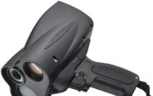
Many of you have seen or even have a second floppy drive in your old computer.
Usually it is located just below the middle of the system unit. The purpose of the device is to read and write floppy disks.
Despite the fact that now there are many other storage media, floppy disks can sometimes come in handy (for example, for flashing a BIOS). But there is no place for them in a modern computer.
In this article, I will tell you in more detail what an FDD is and how to connect it to a new computer.
First of all, I propose to understand what an FDD drive is.
From English, the abbreviation stands for Floppy Disk Drive, which means - floppy disk drive. Like our usual optical drive, this device reads and writes information. But it only works not with optical disks, but with flexible magnetic disks.

It has 2 motors: one is responsible for the rotational speed of the drive, the other moves the read and write head. How fast the first engine works depends on the performance of the floppy disk: they vary between 300-360 rpm.
The second slider is stepping, and moves the heads in discrete intervals along a radial path from the edge to the middle. Unlike modern drive heads, these do not move over the floppy, but along it.
The principle of operation of the device, when it records data, is similar to a tape recorder, that is, the head contacts a magnet. The only difference is that the drive records without high-frequency bias. It remagnetizes the material.
First floppy
The first company to make floppy drives was IBM.
The start was given in the late 1960s by Alan Shugart, who was the leader of the floppy drive development group at this firm.
The first such devices were 8 inches. In 1969, Shugart left the company, followed by more than 100 employees.
After 7 years in his own company Shugart Associates, he developed a miniature 5.25-inch floppy drive, which was the standard for computers.
For Sony, these dimensions seemed large, and in 1983 they released 3.5-inch floppy drives. Hewlett-Packard was the first company that dared to put them into their computers only a year later. Then Apple also "tasted" them, and 2 years later - Apple.

The first 5.25-inch drives had a flexible housing that looked like a sleeve. You could easily bend them with your hands. This disadvantage has been eliminated in 3.5-inch floppy disks, equipped with a plastic case and in addition a special metal shutter that protects the slot for the read head.
Despite the reduction in size, the size of the floppy disks has increased. The maximum capacity of the 5.25-inch variant was 1.2 MB, and the standard 3.5-inch version was 1.44 MB.
Another difference: in order to insert large floppy disks into the drive, it was necessary to turn the lever to fix, the smaller disks drove into the slot automatically.
Ways to connect floppy drives
The interface for FDD that interacts with IBM products is SA-400 (Shugart Associates). Its controller is connected with a 34-pin cable. 5.25-inch devices are equipped with a printed connector. Interested in connecting 3.5 inch drives? Then you will be dealing with a simple male connector.
To connect different drives, a combo cable with four interfaces in pairs can be used. When connecting, keep in mind that the order of the drive (A: or B :) in the BIOS is determined by its location on the cable.
Since current models of computers are not designed to use floppy disks, they do not have devices for them either. Do you really need information from a floppy disk?
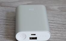
 There is a way out - usb floppy drive.
You guessed it, it connects via a USB port. Plus, not only in the possibility of a connection with any modern computer, but also in the fact that you can take an external drive with you wherever you go.
Why are floppy drives out of use?
You yourself probably guessed that FDDs are no longer used due to the emergence of newer technologies. First, the volume of floppy disks is extremely small in comparison with modern drives. Secondly, their data transfer rates are also poor.
But there are also less obvious reasons. One of them is the fragility of floppy disks. They quickly demagnetized when interacting (not even the closest) with metal objects. For example, you might have traveled with a floppy disk on a tram, metro or trolleybus and lost all information.
Another reason is the vulnerability of the floppy disk design. The edges of the case, even made of tin or plastic, could bend back. This sometimes caused the disc to get stuck in the drive bore. Moreover, plastic is an unreliable material and can break easily.
Consequently, due to the many disadvantages of discs, the need for floppy drives has disappeared.
Despite the exit from widespread consumption, floppy disks and, accordingly, devices for them are still in use. In our country, not all organizations have yet switched to technical equipment of a new type, therefore, in industrial, medical, measuring enterprises, and now you can find floppy drives. They are also used in the music industry.
But such a drive may be useful to you at home, of course, if you are the owner of the old "hardware". With help, you can load an operating system or run a self-loading diagnostic tool. After all, early versions of operating systems do not allow this to be done from optical disks.
Maybe you want to find outdated information in the archives? Then you will probably need a floppy drive too.
Basically, that's all you need to know about the fdd drive.
Visit my blog more often and tell your friends about it on social networks.
Goodbye friends!
Despite the immense popularity of flash drives, optical discs are still in vogue. Therefore, motherboard manufacturers still provide support for CD / DVD drives. Today we want to tell you how to connect them to the motherboard.
How to connect a floppy drive
The optical disc drive is connected in the following way.
- Disconnect the computer, and therefore the motherboard, from the electrical outlet.
- Remove both side covers of the system unit to access the motherboard.
- As a rule, before connecting to the "motherboard", the drive will need to be installed in the appropriate compartment in the system unit. Its approximate location is shown in the image below.

Install the drive with the tray facing out and secure it with screws or a latch (depending on the system unit).
- Next, the most important point is the connection to the board. In the article on motherboard connectors, we briefly touched on the main ports for connecting memory devices. These are IDE (obsolete but still used) and SATA (most modern and widespread). To determine what type of floppy drive you have, take a look at the connection cord. This is how the cable for SATA looks like:

And like this - for IDE:

By the way, floppy disks (magnetic diskettes) drives are connected only via the IDE port.
- Connect the drive to the appropriate connector on the board. In the case of SATA, it looks like this:
In the case of the IDE, like this:
Then you should connect the power cable to the PSU. In the SATA connector, this is the wider part of the common cord; in the IDE, it is a separate block of wires.
- Check if you connected the drive correctly, then replace the system unit covers and turn on the computer.
- Most likely, your floppy drive will not be immediately visible on the system. In order for the OS to recognize it correctly, the drive must be activated in the BIOS. The article below will help you with this.
- Done - Your CD / DVD drive is ready to go.

As you can see, nothing complicated - if necessary, you can repeat the procedure on any other motherboard.


Configuring folder settings and sharing How to find folder options in Windows 10
Disable Windows Wake-up Password Prompt Password Wake-up
Cannot stop service access denied
What is a flagship smartphone: the difference between gadgets What does a flagship smartphone mean
How to make a tablet for orienteering from a navigator